® ® Bowflex® TreadClimber® 1000, 3000 & 5000 Assembly Manual Nautilus® Bowflex® P/N 001-7142 Rev B (01/09) Schwinn® Fitness StairMaster® Universal® Nautilus Institute®
Table of Contents Product Specifications.....................................................................................................................................................1 Important Safety Instructions..........................................................................................................................................2 Before You Assemble.....................................................................................................................................
Product Specifications Physical Dimensions Length Width Height Weight Shipping Weight System Capacities Maximum Weight Capacity Speed 46 inches (117 cm) 28.5 inches (72.5 cm) 55.25 inches (140.5 cm) 185 pounds (84 kg) 220 pounds (100 kg) 300 lbs (136 kgs) TC1000 TC3000 and TC5000 0.5 to 3.8 MPH (0.8 to 6.1KPH ) 0.7 to 4.0 MPH (1.1 to 6.
Important Safety Instructions This icon means a potentially hazardous situation which, if not avoided, could result in death or serious injury. Obey the following warnings: Read and understand all warnings on this machine. Carefully read and understand the Assembly Manual. • Keep bystanders and children away from the product you are assembling at all times. • Do not connect power supply to the machine until instructed to do so.
Before You Assemble Basic Assembly Principles Here are a few basic assembly tips that can make assembly of the Bowflex® TreadClimber® exercise machine quick and easy. 1. Gather the pieces needed for each step prior to starting the step. 2. Turning towards the right tightens all the bolts and locknuts on your Bowflex® TreadClimber®. Turning towards the left, loosens them. 3. All of the tools needed for assembly of your Bowflex® TreadClimber® exercise machine have been included.
Parts Box 1 contains: Qty: 1 Descr: Rear Cover Qty: 1 Descr: Control Panel/Handlebar Assembly Qty: 2 Descr: Plastic Upright Junction Covers Qty: 2 Descr: Left and Right Side Foot Support Platform Qty: 1 Descr: Left Side Plastic Frame Cover Qty: 1 Descr: Right Side Plastic Frame Cover Qty: 1 Descr: Right Side Plastic Drive Cover Qty: 1 Descr: Left Side Plastic Drive Cover 4 Assembly Manual Qty: 2 Descr: Left & Right Hydraulic Cylinder Qty: 1 Descr: Left Upright Support Qty: 1 Descr: R
Parts Box 1 also contains: Qty:1 Assembly Hardware Bag Contains the following: Qty:1 Owner’s Manual Bag Contains the following: • The Bowflex TreadClimber Assembly Guide and Owner’s Manual • (1) Drive Belt • Power Cord • (2) Treadle Decals • (2) Drive Cover Decals • TreadClimber® Safety Key *Note: TC1000 Safety Key plugged into console for shipping.
Hardware Hardware: Qty: 6 Descr: 1/4” x 1” Flat Head Screw Qty: 2 Descr: 5/16” x 1 1/2” Button Head Screw Qty: 16 Descr: #10 Phillips Head Screw Qty: 14 Descr: 5/16” x 1” Button Head Screw Qty: 2 Descr: 5/16” Flat Washer Qty: 12 Descr: 5/16” Flat Washer SAE Qty: 4 Descr: 3/8” Cosmetic Plugs Qty: 2 Descr: 5/16” Acorn Nut Tools: Qty: 1 Descr: #2 Phillips Screwdriver Qty: 1 Descr: 3/16” Hex Key Qty: 1 Descr: 9/16” Open End Wrench Qty: 1 Descr: 5/32” Hex Key Parts: Qty: 1 Descr: Drive Belt 6 As
Assembly Step 1: Put the Treadles on the Base Parts: • TreadClimber® Base Assembly • TreadClimber® Treadle Assembly Hardware: • (4) 3/8” X 1 1/4” Hex Bolts (preassembled) Note: H ardware is only hand tightened. Finish tightening the hardware in Step 1-5 below. Figure 1-1 Tools: • 9/16” Open End Wrench (included) • Scissors or other cutting tool • Ruler Note: This step requires two people. 1-1 Unlock the latch lever (see Figure 1-1).
Assembly Step 2: C onnect the Speed and Step Wires (TC3000 and TC5000 only) Parts: • TreadClimber® Base and Treadle assembly from Step 1 2-1 Connect the Speed Wires (See Figure 2-1). 2-2 Connect the Step Wires (See Figure 2-2). Push any excess wire through holes in frame (See Figure 2-3). Speed Wire Figure 2-1 Note: T he TC1000 is not equipped with step sensor function. Tuck unused step sensor wires through hole in frame.
Assembly Step 3: Lock the Treadles Parts: • TreadClimber® Base and Treadle assembly from Step 2 3-1 Line up the treadles parallel to each other and cut the zip tie connecting them. 3-2 Move the locking lever down and to the left and then up into the locked position until it clicks (See Figure 3-1). 3-3 From the front of the machine, press down on each treadle individually until they lock into the down position.
Assembly Step 5: Attach the Uprights Parts: • TreadClimber® Base and Treadle assembly from Step 4 • (1) Left Upright Support & Hydraulic Cylinder • (1) R ight Upright Support & Hydraulic Cylinder Hardware: • (2) 5/16” x 1” Button Head Screws Tools: Figure 5-1 • 3/16” Hex Key 5-1 Screw a 5/16” x 1” button head screw half way into the outside of the left and right lower upright brackets of the base assembly (See Figure 5-1).
Assembly Step 6: Attach the Upright Junction Parts: • TreadClimber® Base and Treadle assembly from Step 5 • (2) Plastic Upright Junction Covers 6-1 Put the plastic upright junction cover on the top of the left upright support (See Figure 6-1). Note: Make sure the plastic upright junction cover extends to the rear of the machine. 6-2 Repeat on opposite side.
Assembly Step 7: Attach the Console/ Handlebar Assembly Parts: • TreadClimber® Base and Treadle assembly from Step 7 • Console/Handlebar Assembly Hardware: • (6) 5/16” x 1” Button Head Screws • (6) 5/16” Flat Washers SAE Figure 7-1 Tools: • 3/16” Hex Key (included) Note: This step requires two people. 7-1 L ift and position the console/handlebar assembly above the upright supports (See Figure 7-1).
Assembly Step 8: Attach the Cosmetic Plugs Hardware: • (4) Cosmetic Plugs 8-1 Insert the cosmetic plugs into the holes on the top, inside and outside of the left upright support (See Figure 8-1). 8-2 Repeat on opposite side.
Assembly Step 10: Inspect the Assembly 10-1 Remove the plastic film from the console face. 10-2 Inspect all of the attachments and securely tighten all of the bolts before proceeding to Step 11.
Assembly Step 12: Adjust Speed Sensor and Attach the Rear Cover Parts: • TreadClimber® Base and Treadle assembly from Step 11 • (1) Rear Cover Hardware: Figure 12-1 • (4) #10 Phillips Head Screws Tools: • #2 Phillips Head Screwdriver (included) 12-1 H old a stiff business card, ID card, or similar object onto the inside of the drive pulley. Adjust the speed sensor towards the card until it just makes contact. Figure 12-2 12-2 Remove object.
Assembly Step 13: Attach the Drive Covers Parts: • TreadClimber® Base and Treadle assembly from Step 12 • (1) Left Plastic Drive Cover • (1) R ight Plastic Drive Cover Hardware: • (6) #10 Phillips Head Screws Tools: Figure 13-1 • #2 Phillips Head Screwdriver (included) 13-1 A ttach the left and right Plastic Drive Covers to the sides of the base with (6) #10 Phillips Head Screws (3 per side) and the provided #2 Phillips screwdriver (See Figures 13-1). Install upper screw first.
Assembly Step 15: Apply Decals Parts: • TreadClimber® Base and Treadle assembly from Step 14 • (2) Treadle Decals • (2) Drive Cover Decals Treadle decal 1 per side Drive decal 1 per side Tools: • #2 Phillips Head Screwdriver (included) 15-1 Clean the application surface with a wet cloth and dry thoroughly with a towel. 15-2 Remove the relase backing on the decal. Figure 15-1 15-3 Center the decal on the appropriate application surfaces (See Figure 15-1) for locations.
Assembly Step 18: C alibration (TC3000 and TC5000 only) Note: D uring calibration, observe the walking belt alignment. Belts do not need to be perfectly centered, but if they are far enough from center to cause a scraping sound, follow the belt alignment instructions in the Owner’s Manual. Figure 18-1 Main Power Switch “On” Failure to calibrate your machine prior to use could result in machine failure and could cause injury.
Assembly If Calibration Fails (Screen Displays “Cal Fail” Message): This error usually indicates that the console is unable to determine the speed of the belts. Take the following steps: 1. Unplug the unit and remove the three back covers. 2. Hold a stiff business card, ID card, or other similar onto the inside of the drive pulley. Adjust the speed sensor towards the card until it just makes contact. 3. Remove the card. 4. Plug unit in and recalibrate.
Troubleshooting Condition / Problem Unit will not power up/turn on/ start Things to Check Outlet Make sure outlet is functioning correctly. Verify this by plugging another object (ex: lamp) into the outlet. If outlet is connected to a light switch, check to make sure it is on. If outlet is not functioning find a working outlet. Power cord not plugged in Make sure the power cord is firmly secured to A/C inlet on the unit and firmly inserted into a non-GFI wall socket.
Troubleshooting Condition / Problem Hesitation or belt slipping when walking on unit Things to Check Solution Belt tension If belt hesitates or slips when walking on unit it may be caused by either a loose walking belt or a loose drive belt. To determine the cause perform the following test: Stand beside TreadClimber® fitness machine and set speed to 2 MPH. Step on one treadle and attempt to stop movement.
Troubleshooting Condition / Problem Knocking noises when unit is operating in TreadClimber or stepper mode, but not in treadmill mode Belts stop turning and “err LS” or “err OS” is displayed 22 Assembly Manual Things to Check Solution Treadle alignment Make sure treadles are centered between uprights and treadle is not contacting upright during use. If not centered remove rear plastic covers to access rear baseplate bolts. Loosen bolts slightly to allow treadles to be centered.
Exploded Views Ordering Replacement Parts Call a Bowflex® TreadClimber® Representative at 1-800-NAUTILUS (1-800-628-8458) to order replacement parts and get assistance with your specific replacement or service requirements.
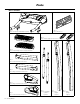
Exploded Views Walking Belts R. Rear Belt Guide (L. Rear Belt Guide Not Shown) Deck Front Roller Keeper R. Outer Treadle Skin Foot Platform Front Roller Bracket Front Roller Inner Treadle Skin (L & R) Front Roller Bracket L.
Main Frame Left Drive Cover Left Frame Cover Base Cover Safety Plate Red Cap TC Foot gs Plu Wheels Lever Latch Bracket gs Plu Rear Cover Cord Bracket Locking Latches Latch Offset Bracket Latch Arm Assembly Manual Ten Motor Base M r oto Kit tor Mo n sio Right Drive Cover Right Frame Cover Motor Controller Exploded Views 25
Important Contact Numbers UNITED STATES OFFICES TECHNICAL/CUSTOMER SERVICE Phone: 800-NAUTILUS (800-628-8458) E-mail: tcinquiry@nautilus.com CORPORATE HEADQUARTERS Nautilus, Inc. World Headquarters 16400 SE Nautilus Drive Vancouver, Washington, USA 98683 Phone: (800) NAUTILUS (800) 628-8458 INTERNATIONAL OFFICES INTERNATIONAL CUSTOMER SERVICE Nautilus International S.A. Rue Jean Prouvé 1762 Givisiez / Switzerland Tel: + 41 26 460 77 77 Fax: + 41 26 460 77 70 E-mail: technics@nautilus.
® ® Printed in China ©2008. Nautilus, Inc. All rights reserved. Nautilus, the Nautilus Logo, TreadClimber, the TreadClimber Logo, Bowflex, Bowflex Logo, StairMaster and Nautilus Institute are either registered trademarks or trademarks of Nautilus, Inc. Schwinn is a registered trademark. All other trademarks are owned by their respective companies. Nautilus, Inc., World Headquarters, 16400 SE Nautilus Drive, Vancouver, WA 98683 1-800-NAUTILUS www.nautilus.