
TreadClimber Assembly Manual


10
Assembly Manual
Assembly
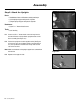
Figure 5-1
Step 5: Attach the Uprights
Parts:
• TreadClimber
®
Base and Treadle assembly from Step 4
• (1) Left Upright Support & Hydraulic Cylinder
• (1) Right Upright Support & Hydraulic Cylinder
Hardware:
• (2) 5/16” x 1” Button Head Screws
Tools:
• 3/16” Hex Key
5-1 Screw a 5/16” x 1” button head screw half way into the
outside of the left and right lower upright brackets of the
base assembly (See Figure 5-1).
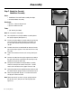
5-2 Put the left upright on the left upright bracket (See Figure
5-2) so that it rests on the button head screw (See Figure
5-3). The cylinder bracket will be at the top and face the
rear of the machine.
Note: Make sure the decal on the upright support faces outward from
the machine.
5-3 Repeat on the opposite side.
Figure 5-2
Figure 5-3