The Bowflex Revolution®XP Home Gym Assembly Instructions P/N: 001-7057 Rev $ ( /0 )
Table of Contents Before You Start ....................................... 2 Tools You Will Need / Hardware Contents.... 3 Box Contents............................................ 6 Assembling Your Bowflex Revolution ..........10 Important Contact Numbers ......................29 Before You Start Before You Assemble Select where you are going to locate your Bowflex Revolution®XP carefully. The best place for your Bowflex Revolution®XP is on a hard, level surface.
Tools You Will Need Hex Wrenches Are Provided in the Box These Tools Are Not Provided in the Box Phillips Head Screwdriver 3/32” Allen Wrench for #8 Allen Screws 3/4” and 9/16” Wrenches or Adjustable Wrenches 5/16” Allen Wrench for 1/2” Allen Screws 7/32” Allen Wrench for 3/8” Allen Screws 1/8” Allen Wrench for Top Cover Screws * Tool and Hardware specifications subject to change without notice.
Hardware 12 7 10 9 2 5 2 6 6 Only two needed for XP model. Use 4 for FT model. 3 8 3 4 2 1 11 Used on the FT model only Hardware Card (Box 3) ITEM NO. QTY.
Hardware 9 8 6 5 2 3 7 4 1 Hardware Card (Box 4) ITEM NO. QTY.
Box Contents BOX 1 1 3 2 2 6 5 4 Box 1 Contents ITEM QTY.
Box Contents BOX 2 8 10 9 7 Box 2 Contents ITEM NO. QTY.
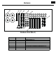
Box Contents BOX 3 12 16 21 17 11 15 18 13 19 14 20 Box 3 Contents ITEM NO. QTY.
Box Contents BOX 4 33 32 29 24 30 34 35 26 28 31 25 22 23 27 Box 4 Contents ITEM NO. QTY.
Assembly (Unboxing) WA R N I N G Warning: The Bowflex Revolution®XP Home Gym is very heavy. Whenever possible use two people to unbox the main unit. We have designed the packaging to make unboxing the main unit as safe and easy as possible. NOTE: Some of the hardware needed for unboxing is located on the Box 3 Hardware Card Top layer of styrofoam Open top flaps Step 1 1-1 Open the top flaps of Box 2 (Figure A) and split the corners along the perforations to expose the top layer of styrofoam.
Assembly (Unboxing) Transport Wheel Transport Wheel Plate Step 3 Assemble Rear Stabilizer Transport Wheel Plate Parts: • Rear Stabilizer (Box 2) • Rubber Pads (Box 3 hardware card) • Transport Wheels (Box 3) Holes Tools: • 7/32” Allen Wrench 3-1 Insert Transport Wheels into Rear Stabilizer making sure that the holes in the Stabilizer and the plates on the Transport Wheels are pointing up. Rear Stabilizer 3-2 Install and completely tighten the hardware.
Assembly (Unboxing) Step 4 Install Rear Stabilizer Parts: • Rear Stabilizer (From Step 3) Tools: • 5/16” Allen Wrench • 7/32” Allen Wrench • 3/4” Wrench or Adjustable Wrench 4-1 Place the Rear Stabilizer in the bracket on the Main Frame with the wheels pointing away from the frame. Make sure the two bolt holes in the Rear Stabilizer are pointing downward. 4-2 Install but do not tighten two 3/8”x3/4” Allen Bolts and 3/8” washers (Box 3 Hardware Card) in the underside of the Rear Stabilizer.
Assembly (Unboxing) Step 5 Install Stabilizers and Lower Lat Connector Parts: • Right and Left Stabilizer (Box 3) • Lower Seat Connector (Box 4) Tools: • 5/16” Allen Wrench • 3/4” Wrench or Adjustable Wrench 5-1 Insert Lower Seat Connector into the Main Frame with the threaded hole on the flat side pointing down as shown. 5-2 Align the Right and Left Stabilizers with the holes in the Main frame. 5-3 Install but DO NOT TIGHTEN the hardware.
Assembly (Unboxing) Step 6 3/8 x 2 3/4 ” Button Head Cap Screw Parts: • Platform (Box 3) • Foot Caps (Box 2) Tools: • 7/32” Allen Wrench • 9/16” Wrench or Adjustable Wrench 3/8” Washer 6-1 Align Platform with Stabilizers making sure the rubber pads are pointing downward. 3/8” Nylock Nut 6-2 Install DO NOT TIGHTEN the hardware. 3/8” Washer 6-3 Install Foot Caps onto the ends of the Stabilizers.
Assembly (Unboxing) Step 8 8-1 Lift the box up and off of the styrofoam packing. 8-2 Separate the styrofoam packing. Remove plastic wrapping from the engine. Separate styrofoam packing Lift box Styrofoam packing Step 9 Tools: • 5/16” Allen Wrench 9-1 Install one 1/2”x3/4” Allen Bolt. 1/2”x 1” Allen Bolt 9-2 Make sure Platform is flat and level and completely tighten hardware from steps 5 through 9.
Assembly Step 10 Remove Top Cover Top Cover Remove screws Tools: • 1/8” Allen wrench 10-1 Use a 1/8” Allen Wrench to remove the four screws in the Top Cover, then remove the Top Cover and set it aside. Set screws aside for Step 16. Remove front piece first Step 11 Remove Styrofoam Inner Packing 11-1 Remove and discard the three pieces of Styrofoam Inner Packing. Note: You must open the plastic bag and remove each piece of styrofoam individually.
Assembly Main unit Step 12 Install Tension Shaft Parts: • Main Unit • Shaft (Box 3) 12-1 Align the rounded side of the Tension Shaft with the rounded side of the hole in the Main Unit and slowly slide the Shaft through until it clicks into place. Rounded edge on top Shaft If the Shaft is obstructed inside the Main Unit, loosen the tension screws in the Tension Shaft Holder (see Step 13).
Assembly Step 13 Tighten Tension Shaft Holder Tools: • 7/32” Allen Wrench 13-1 Use a 7/32” Allen Wrench to tighten the Tension Shaft Holder by tightening the screws in numerical order shown on the tensioner. Tighten the two screws marked 1, then the two marked 2, etc. Note: Do not replace Top Cover at this time. Tension screws Tighten screws in order 1&1 , 2&2, 3&3, then 4&4.
Assembly Side view of pre-tension SpiraFlex ® pack Step 14 Install Pre-Tension SpiraFlex® Packs. Tools: • 3/32” Allen Wrench (Box 1) Pre-tension Hooks toward SpiraFlex®Pack main unit #8-32 X 3/8” Allen screw Parts: • Pre-tension SpiraFlex® Packs (Box 1) 14-1 Align the rounded edge of the Pre-tension SpiraFlex® Pack with the rounded edge of the Tension Shaft and slide it all the way onto the shaft.
Assembly Step 16 Replace Top Cover Make sure inside edges of Shroud fit in slots on Top Cover Parts: • Top Cover Allen Screw Top Cover Rear Slots Front Inside Edge Tools: • 1/8” Allen Wrench Tab Shroud 16-1 If the screws are still in the Top Cover from Step 1, remove them to avoid dropping them into the Main Unit. 16-2 Replace the Top Cover front end first. Make sure inside edge of the Shroud fits into the slots in the Top Cover.
Assembly Adjusting Cable Tension (continued) There are tension knobs on each side of the machine. To increase cable tension, pull knob and turn the large pulley clockwise. You’ll know when you have enough tension when the cable retracts and the cable clip touches the pulley. The cable clip should stop here. Large pulley. This is what you need to turn to increase the tension on the cable. Pull the tension knob and use your other hand to turn the large pulley clockwise.
Assembly Step 18 Install Seat Tube 3/8”x 4” Button Head Cap Screw Seat Support Tube Parts: • Seat Tube (Box 4) 3/8” Nylock Nut Tools: • 7/32” Allen Wrench 3/8” Narrow Washer 18-1 Align the Seat Tube with the holes in the Seat Support Plates and the Lower Seat Connector. 18-2 Install and completely tighten the hardware from step 17 and 18.
Assembly Step 20 Install Cable Hooks Parts: • Rope Hooks (Box 3 Hardware Card) Tools: • 5/16” Allen Wrench 20-1 Align the Hooks with the holes in the Main Frame with the tabs on the hooks inserted into the slots in the Main Frame. 20-2 Install and completely tighten the hardware. 1/2” Nylock nut NOTE: The remaining holes in the Main Frame just above the Hook Holes should be plugged with two 1/2” plugs from the Box 2 hardware card. The remaining plugs are not needed on this unit and can be discarded.
Assembly Pulley Step 21 Install Pulleys Hook Bolt Spring Parts: • Pulley Components (Box 3) Spring Cap Hook Bolt Tools: • Screwdriver Spring Cap Hex Nut (discard) NOTE: Remove and discard the hex nut to disassemble the Pulley components. 21-1 Place a Spring Cap over a threaded hole in a Stabilizer and screw the Hook Bolt into the hole ONLY about three turns. (Figure A) 21-2 Place the Spring down over the Hook Bolt. Compress the Spring and hook the Eyelet under the Pulley to the Hook Bolt.
Assembly Step 22 Install Back Pad Seat Back Parts: • Back Pad (Box 4) • Back Pad Bracket (Box 4) Seat Back Bracket 5/16” Washer Tools: • 3/16” Allen Wrench 22-1 Align the Back Pad with the lower 4 holes in the Back Pad Bracket. The upper holes are not used with this pad. 22-2 Install and completely tighten the hardware.
Assembly Attaching Seat and Back Pad Attach the Seat and Back Pad to the Main unit by placing the Upper Hooks onto the respective Upper Post and rotating the Lower Hook into position. Once the Seat Pad is in postion, insert the Locking Pin through the hole behind the Lower Hook to secure the pad to the Seat Tube.
Assembly Roller Pad Step 24 Assemble Leg Extension Parts: • Foam Roller Pads Pad (Box 4) • Roller Tubes (Box 4) • Leg Extension Assembly (Box 4) • End Caps (Box 4 Hardware Card) • Leg Extension Pin (Box 4 Hardware Card) Leg Extension Assembly Leg Extension Pin Roller Tube 24-1 Slide the Roller Tubes through the holes in the Leg Extension Assembly followed by the Roller Pads and End Caps. 24-1 Place the Leg Extension Pin through Leg Extension Assembly and Pivot Tube.
Assembly Step 25 Install Cables Parts: • Ropes (Box 3) 25-1 Remove the Ball End from the cable by pressing the insert out of the ball (Figure A) and slide the ball off of the cable. 25-2 Route the cable under the Pulley closest to the Main Unit and reinstall the Ball End (Figure B). Cable Pulley Figure A NOTE: When not in use, store the cable by wrapping it around the Cable Hooks as shown.
Step 26 Apply Revolution XP Decal Parts: • Revolution® XP Decal (Box 4 Documentation Kit) 26-1 Apply the Decal to the Platform in the indented area as shown. .
Step 27 Final Inspection Please inspect your machine to ensure that all fasteners are tight and components are properly assembled. Review all warnings affixed to machine. Congratulations! You have successfully completed assembly of your Bowflex Revolution® XP home gym! 7! 2 . ) . ' Failure to visually check and test assembly before use can cause damage to the Bowflex Revolution® XP home gym and serious injury to users and bystanders and can also compromise the effectiveness of your exercise program.
Important Contact Numbers If you need assistance, please have both the serial number of your machine and the date of purchase available when you contact the appropriate Nautilus office listed below. Please record the following information for future reference. Serial Number Date of Purchase OFFICES IN THE UNITED STATES: INTERNATIONAL: E-mail: customerservice@nautilus.com • TECHNICAL/CUSTOMER SERVICE Nautilus, Inc.
This manual is written and designed by industry professionals. If you have any questions regarding your Bowflex Revolution®XP Home Gym or any instructions found in this manual, please call 1-800-NAUTILUS (800-628-8458) for assistance. ©200 Nautilus Inc. All rights reserved. 16400 S.E. Nautilus Drive, Vancouver, Washington, USA 98683. Bowflex, Bowflex Revolution, and the Bowflex and Nautilus logos are either registered trademarks or trademarks of Nautilus, Inc.