
Owner manual

A-5
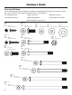
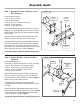
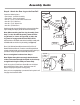
Step 4 - Attach the Chest Bar with Pulleys to
the Main Assembly
Locate the following items:
• From Step 3 - Main Assembly
• Item #6 - Chest Bar
• Item #31 - Chest Pulleys
• Item #K - (2) 3/8" X 5" Button Head Screws
• Item #N - (4) 3/8" Washers
• Item #O - (2) 3/8" Nylock Nuts
Line up the bolt holes in the brackets on the Chest Bar (Item
#6) with the lowest bolt holes on the Lower Lat Tower, as
shown in Figure 4.
Place (2) 3/8" Washers (Item #N) over the end of (2) 3/8” X 5"
Button Head Screws (Item #K) - one washer per screw. Insert
the screws through the lined up holes in the Chest Bar and
the Lower Lat Tower, and secure each screw by placing (1)
3/8" Washers and (1) 3/8" Nylock Nuts (Item #O) over the end
of each screw.
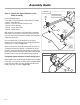
Remove the (2) 1/4” X 1/2” Socket Head Cap Screws from
the underside of each end of the Chest Bar. Slide the Chest
Pulleys (Item #31) over each end of the Chest Bar. Install
(1) 1/4” X 1/2” Socket Head Cap Screw into the hole on the
underside of each end of the Chest Bar. This prevents the
Chest Pulleys from sliding off
Completely tighten hardware installed during Step 4.
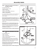
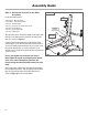
Step 5 - Attach the Seat Bracket to the Seat
Pad
Locate the following items:
• Item #7 - Seat Pad
• Item #8 - Seat Bracket
• Item #C - (4) 5/16" X 3/4" Button Head Screws
• Item #M - (4) 5/16" Washers
Place the Seat Pad (Item #7) on the floor, cushion-side down.
Position the Seat Bracket (Item #8) so the cut-out is toward the
angled edge of the Seat Pad. Align the four holes in the Seat
Bracket with the four holes in the Seat Pad.
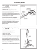
Place (4) 5/16" Washers (Item #M) over (4) 5/16" X 3/4" Button Head
Screws (Item #C) - one over each screw, and use those screws to
secure the Seat Bracket to the Seat Pad.
Completely tighten hardware installed during Step 5.
Figure 5
M
C
8
7
Cut-out
Angled
Edge
Base Platform/
Lower Lat Tower
Assembly
Figure 4
6
O
K
N
Chest Bar
Brackets
Assembly Guide