
Service manual


28
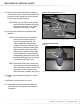
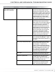
12.0 - LOCKING MECHANISM ADJUSTMENT
Tools Needed:
• Phillips Screwdriver
• 1/2 inch wrench
• 3/16 Allen Wrench
NOTE: If using a powered driver, it must be on the
“LOW TORQUE” setting, otherwise it will strip
screws.
12-1 Unplug machine from wall outlet and from front of unit.
12-2 Wait 5-minutes after unplugging machine to ensure
there is no residual power.
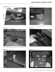
12-3 Remove the front base plastic (4 screws) see Figure 1.
12-4 Remove the right and left top base plastic (3 screws
each) see Figure 1.
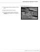
12-5 Place the lockout lever in the position where the
front faceplate captures the lever in the down
position. This is the TreadClimber® mode position
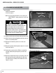
(treadles freely rotate). Adjust the major adjustment
by pulling the cable through the junction plastic
and metal cylinder cable housing, so that the cable
is tight and the locking pins are pulled clear of the
dependency teeter. Secure the cable position by
tightening the set screw with a screwdriver. See
Figure 2 and 3.
12-6 Release the lockout lever from the face plate and
make sure the pins engage the teeter and lockout
treadles. The fine tune adjustment can be used to
tension or loosen the cable as needed. See Figure 4.
MECHANICAL SERVICE GUIDE
Figure 1:
Figure 2: Unlock Treadles Position
Figure 3: Major Adjustment
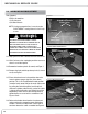
AS LONG AS THE TREADCLIMBER
®
FITNESS
MACHINE IS PLUGGED INTO A POWERED OUTLET
AND THE POWER SWITCH IS ON, THE UNIT IS
RECEIVING POWER, EVEN IF THE DISPLAY IS
TURNED OFF. ALWAYS UNPLUG THE POWER CORD
FROM THE OUTLET AND WAIT 5-MINUTES BEFORE
PERFORMING REPAIRS OR MAINTENANCE.
7 ! 2 . ) . '
! 4 4 % . 4 ) / .
$ ! . ' % 2
)--%$)!4%!#4)/.2%15)2%$
# ! 5 4 ) / .
Right & Left Top Base
Plastic Covers
Front Base
Plastic Cover
Treadle Lockout Lever
Treadle Lockout Lever
Faceplate
Setscrew
Junction Plastic
Cable