SERVICE MANUAL SERVICE MANUAL BOXLIGHT CP-320t ORIGINAL VERSION Chassis No. MA3-CP-320t00 NOTE: Match the Chassis No. on the unit’s back cover with the Chassis No. in the Service Manual. If the Original Version Service Manual Chassis No. does not match the unit’s, additional Service Literature is required.You must refer to “Notices” to the Original Service Manual prior to servicing the unit. PRODUCT CODE 1 122 157 04 (MA3E) REFERENCE NO.
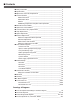
■ Contents ■ ■ ■ ■ Safety Instructions ________________________________________________3 Specifications ____________________________________________________4 Adjustments after Parts Replacement ________________________________5 Circuit Protections ________________________________________________6 ● Thermal switch ____________________________________________6 ● Interlock switch ____________________________________________6 ● Fuse ____________________________________________________6 ● Warning temperature an
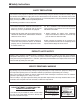
■ Safety Instructions SAFETY PRECAUTIONS WARNING: The chassis of this projector is isolated (COLD) from AC line by using the converter transformer. Primary side of the converter and lamp power supply unit circuit is connected to the AC line and it is hot, which hot circuit is identified with the line ( ) in the schematic diagram. For continued product safety and protection of personnel injury, servicing should be made with qualified personnel. The following precautions must be observed.
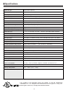
■ Specifications Projector Type Multi-media Projector Dimensions (W x H x D) 13.11” x 3.52” x 9.96” (333mm x 89.5mm x 253mm) Net Weight 9.5 lbs (4.3 kg) LCD Panel System 0.8” TFT Active Matrix type, 3 panels Panel Resolution 1024 x 768 dots Number of Pixels 2,359,296 (1024 x 768 x 3 panels) Color System 6 color system (PAL, SECAM, NTSC, NTSC4.43, PAL-M and PAL-N) High Definition TV SIgnals 480i, 480p, 575i, 575p, 720p. 1035i and 1080i Scanning Frequency H-sync. 15 ~ 100kHz, V-sync.
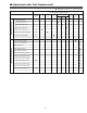
■ Adjustments after Parts Replacement ● : Adjustment necessary ❍ : Check necessary Disassembly / Replaced Parts LCD/ Prism Ass’y Condenser Lens Condenser Lens-Out Relay Lens-Out Polarized glass R G B P. F.
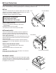
■ Circuit Protections This projector provides the following circuit protections to operate in safety. If the abnormality occurs inside the projector, it will automatically turn off by operating one of the following protection circuits. ● Fuse The fuse is located inside of the projector. When either the LAMP indicator or the READY indicator is not illuminated, fuse may be opened. Check the fuse as following steps. It should be used the specified fuse as follows; Fuse Line Filter Board Fuse Part No.
Circuit Protections ● Warning temperature and power failure protection The projector will be automatically turned off when the internal temperature of the projector exceeds the normal operating temperature, or the cooling fans stop, or the power supplies in the projector are failed. - If the TEMP WARNING indicator (red) is flashing, it may detect the abnormal temperature inside the projector.
■ Mechanical Disassemblies Mechanical disassemble should be made following procedures in numerical order. Following steps show the basic procedures, therefore unnecessary step may be ignored. Caution: The parts and screws should be placed exactly the same position as the original otherwise it may cause loss of performance and product safety. Screws Expression (Type Diameter x Length) mm z Cabinet Top and Control Panel removal 1 Remove 4 screws A (M3x6) to take the Cabinet Top Ass’y upward off.
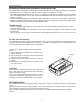
Mechanical Disassemblies c AV, DVI, Temp Board and Speaker removal 1 Remove 1 screw A (M4x8) to release grounding wires. 2 Pull the Rear Panel ass’y upward. 3 Remove 4 screws B (T3x6) and remove the AV Board. 4 Remove 4 screws C (T3x6) and remove the DVI Board. 5 Remove 4 screws D (T2.6x6) and remove the speaker. 6 Remove 1 screws E (T3x8) and remove the Sensor Board. Temp board E DVI board C B C B B B C AV board D D A Speaker Fig.
Mechanical Disassemblies b Lamp Ballast Unit removal 1 Remove 1 screw A (M3x4) and remove SW902, and then remove 1 screw B (M3x6) and disconnect the Lamp Socket. 2 Remove 2 screws C (M3x6) to take the Lamp Ballast ass’y upward off. 3 Remove 2 screws D (T2x6) to take the isolation sheet off. 4 Remove 4 screws E (T3x6) to take the lamp ballast board off. C D D E C E E Isolation sheet E B Lamp ballast board Lamp ballast socket A SW902 Fig.
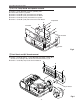
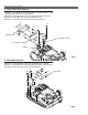
Mechanical Disassemblies m Power Box Cover and Fans(FN901, FN906) removal 1 Remove 4 screws A (M3x12) to take the Fan(FN901) off. 2 Remove 4 screws B (M3x8) to take the Fan(FN906) off. 3 Remove 3 screws C (M3x6) to take the Power Box Cover A upward off. A FN906 A A C B B B B C C Power box cover FN901 Fig.7 , Optical Unit removal (1) 1 Remove 1 screw A (M3x6) to take the Lamp Cover off. 2 Loosen 3 screws B to take the Lamp assembly by pulling the handle. Step to next procedure.
Mechanical Disassemblies , Optical Unit removal (2) Step from previous procedure. 3 Remove 6 screws C (M3x8) to take the Optical Unit upward upward off. To mount optical unit, mount optical unit first then mount the Lamp assembly and Lamp Cover. C C C C C C Optical unit Fig.8-2 . Power and P.F. Board removal 1 Remove 4 screws A (T3x6), 4 screws B (T3x8) to take the Power Board ass’y upward off. 2 Remove 4 screws C (M3x6) to take the P. F. Board from the Power Board.
Mechanical Disassemblies ⁄0 Fan (FN905) removal 1 Remove 1 screw A (M3x6) and take a Washer, A Spring and Interlock Switch lever. 2 Pull the Fan and duct ass’y upward, then remove the Interlock switch lever 2 screws B (M3x6) to take the Fan (FN905) off. B B FN905 Fig.10 ⁄1 Fans (FN902, FN903, FN904) removal A A 1 Remove 8 screws A (T3x8) and to take the Fan A Duct Top off and remove the Fans (FN902, FN903, FN904).
■ Optical Parts Disassemblies Before taking this procedure, remove Cabinet Top and Main Board following to the “Mechanical Disassemblies”. Disassembly requires a 2.0mm hex wrench. z Projection Lens removal 1 Remove the Front Panel following to “Front Panel Removal” on “Mechanical Disassemblies”. 2 Remove 4 screws (M3x10) to take the Projection Lens ass’y off. Fig.1 x Integrator Lens-In disassembly 1 Remove 2 screws A (M2.5x6) and pull the Integrator Lens-In ass’y upward.
Optical Pats Disassemblies c Condenser lens disassembly 1 Remove 2 screws A (M2.5x6) and pull the Condenser Lens ass’y upward. 2 Remove 4 screws B (M2x4) to take the Lens off from the holder. A A B Condenser Lens Holder B B B * Lens should be placed as the flat surface side comes to the holder side. Fig.3-2 Fig.3-1 v Condenser Lens-Out disassembly 1 Remove 2 screws A (M2.5x6) and pull the Condenser Lens-Out ass’y upward. 2 Remove 2 screws B (M2x4) to take the Lens off from the holder.
Optical Parts Disassemblies b Relay Lens-Out disassembly 1 Remove 2 screws A (M2.5x6) and pull the Relay Lens-Out ass’y upward. 2 Remove 2 screws B (M2x4) to take the Lens off from the holder. Note: There is no mounting direction of the lens. A B A Holder B Relay Lens-Out Fig.5-2 Fig.5-1 n Polarized Glass-In removal 1 Remove each screw (M2.5x6) and pull the Polarized Glass-In ass’y upward. 2 Unhook the stoppers and take the glass off upward.
Optical Parts Disassemblies m Polarized Glass-Out/Pre-Polarized Glass removal 1 Remove 4 screws A (M2.5x4) and take the LCD/Prism ass’y off upward from the optical unit. 2 Remove each screw B and take the glass off upward. Note: The G-LCD and B-LCD panels have a pre-polarized glass respectively as shown in Fig.7-2. A Note: Do not replace the LCD panel separately otherwise it can not obtain proper picture.
Optical Parts Disassemblies . Locations and Directions Key No. When the optical parts in the optical unit mounting or assembling, the parts must be mounted in the specified location and direction as shown in figure below.
■ LCD Panel/Prism Ass’y Replacement IMPORTANT NOTICE on LCD Panel/Prism Ass'y Replacement LCD panels used for this model can not be replaced separately. Do not disassemble the LCD Panel/Prism Ass’y. These LCD panels are installed with precision at the factory. When replacing the LCD panel, should be replaced whole of the LCD panels and prism ass’y at once. After replacing LCD Panel/Prism ass’y, please check the following points.
■ Lamp Replacement WARNING: - For continued safety, replace with a lamp assembly of the same type. - Allow the projector to cool for at least 45 minutes before you open the lamp cover. The inside of the projector can become very hot. - Do not drop the lamp module or touch the glass bulb! The glass can shatter and cause injury. Procedure 1 Turn off the projector and disconnect the AC cord. Allow the projector to cool for at least 45 minutes. 2 Loosen 1 screws with a screwdriver and open the lamp cover.
■ Optical Adjustments Before taking optical adjustments below, remove the Cabinet Top and Main Board following to the “Mechanical Disassemblies” Adjustments require a 2.0mm hex wrench and a slot screwdriver. When you adjust Condenser lens, Condenser lens-out or Relay lens adjustment, you need to disconnect some connectors and FPC cables of LCD panels on the main board.
Optical Adjustments Condenser Lens adjustment 1 Turn the projector on by a state of without FPC cables. 2 Project only green light on the screen. 3 Adjust the adjustment base of condenser lens assy to make color 4 uniformity in green. 1) If the shading appears on the left or right of the screen as shown in Fig.2-1, loosen 2 screws A with the 2.0mm hex driver, and adjust the slot B to make color uniformity in green by using a slot screwdriver.
Optical Adjustments Condenser Lens-Out adjustment 1 Turn the projector on by a state of without FPC cables. 2 Project green and blue lights on the screen. 3 Adjust the adjustment base of condenser lens-out assy to make color uniformity in cyan. 1) If the shading appears on the left or right of the screen as shown in Fig.3-1, loosen 1 screw A with the 2.0mm hex driver, and adjust the slot B to make color uniformity in cyan by using a slot screwdriver.
Optical Adjustments Relay lens-Out adjustment 1 Turn the projector on by a state of without FPC cables. 2 Project all of lights on the screen. 3 Adjust the adjustment base of relay lens assy to make color uniformity in white. 1) If the shading appears on the left or right of the screen as shown in Fig.4-1, loosen 1 screw A with the 2.0mm hex driver, and adjust the slot B to make color uniformity in white by using a slot screwdriver.
■ Electrical Adjustments ● Service Adjustment Menu Operation To enter the service mode To enter the “Service Mode”, press and hold the MENU and IMAGE button on the projector at the same time for more than 3 seconds. The service menu appears on the screen as follows. To adjust service data Select the adjustment item no. by pressing the e or d button, and change the data value by pressing the 7 or 8 button. Refer to the “Service Adjustment Data Table” for further description of adjustment item no.
Electrical Adjustments ● Circuit Adjustments CAUTION: The each circuit has been made by the fine adjustment at factory. Do not attempt to adjust the following adjustments except requiring the readjustments in servicing otherwise it may cause loss of performance and product safety. [Adjustment Condition] ● Input signal Video signal .......................... 1.0Vp-p/75Ω terminated, 16 steps gray scale (Composite video signal) Computer signal .................... 0.
Electrical Adjustments x Signal Center adjustment v Gain adjustment [PC] 1. Receive the 16-step grey scale computer signal with Computer [Analog RGB] mode. 2. Enter the service mode. 3. Connect a digital voltmeter to test point “TP505R” (+) and chassis ground (-). 4. Select item no. “1 and adjust the voltage to be 7.50 ±0.1Vdc by changing the Data value. 5. Connect a digital voltmeter to test point “TP503G” (+) and chassis ground (-). 6. Select item no. “2” and adjust the voltage to be 7.50 ±0.
Electrical Adjustments n Gain adjustment [Component] , Gamma Gain adjustment [AV] 1. Receive the 16-step gray scale component video signal [480i] with Video [Y,Cr,Cb] mode. 2. Enter the service mode. 3. Connect an oscilloscope to test point “TP505R” (+) and chassis ground (-). 4. Select item no. “4” and adjust the amplitude “a” to be minimum by changing the Data value. 5. Connect an oscilloscope to test point “TP503G” (+) and chassis ground (-). 6. Select item no.
Electrical Adjustments ⁄0 Signal Offset adjustment [PC] ⁄2 White Balance adjustment 1. Receive the 16-step gray scale computer signal with Computer [Analog RGB] mode. 2. Enter the service mode. 3. Connect an oscilloscope to test point “TP503G” (+) and chassis ground (-). 4. Select item no. “10” and adjust the amplitude “a” to be 2.4 ±0.1V by changing the Data value. [PC WHITE BALANCE ADJUSTMENT] 1. Receive the 16-step gray scale computer signal with Computer [Analog RGB] mode. 2.
TP3531 -30TP12V2 TP12V1 TP505R TP506R K5R IC531 TPV3143 IC3101 IC401 K5G K8B TP504G TP503G TP502B TP501B TPHS IC801 IC501 K8A TPVS IC301 TPDHS TP12B TPDVS TP6201 K8U K8H K8N TPV3148 TP6221 IC811 TP6241 K8P TP3501 K5B IC3801 TP12R TP12G Electrical Adjustments Test Points and Locations ● MAIN BOARD
Electrical Adjustments ● Service Adjustment Data Table These initial values are the reference data written from the CPU ROM to memory IC when replaced new memory IC. The adjustment items indicated with “✻” are required to readjust following to the “Electrical adjustments”. Other items should be used with the initial data value. Initial Item No.
Electrical Adjustments Initial Item No.
Initial Item No. Name 131 272 273 274 275 276 277 278 279 297 298 299 300 301 302 303 304 305 306 307 308 309 310 311 312 313 314 315 316 317 318 319 320 321 322 323 324 325 326 327 328 329 330 331 332 333 334 335 336 337 338 339 340 341 342 343 344 350 351 352 353 354 Lamp use time in min.
DVI-I D-SUB MNTOUT H/V H/V IC221 -34- AUDIO IC5341 G-SYNC FAN VSYNC HSYNC IC7201 MATRIX IC5351 INVERTER FAN FAN CONTROL -5V 6V 15.5V GR GG GB FAN CONTROL IC6301 SYNC-SW R/C DVI PC/AV V H CR Y CB IC301 SCAN CONVERTER SYSTEM CONTROL RC TXD,RXD USB IC3851 SERIAL CONT-2 VHS VVS Y,C PC/AV G-SYNC IC8201 A/D POWER D0-7 A0-A17 IC3801 SERIAL CONT-1 IC3871 RS-232C Audio-Out IC3101 VIDEO DECODER PC1/PC2 IC5361 SYNC-SEP.
DVI-I -35- COMPONENT C-VIDEO Y 14,8 1 C 8 Y VIDEO/Y 2 D-SUB S-VIDEO S-VIDEO/VIDEO IC2101 VIDEO-SW 7,2,12 3 5 6 PC/AV C Y 9 2 10 3 13 PC/AV PC1/PC2 VIDEO/Y 1 5 12 14 IC5361 SYNC.SEP. 28 V H 5 3 2 TPV3148 TPY3147 TPV3143 TP3101 TP3102 TP3103 G-SYNC IC6241 IC6221 IC5341 SYNC.
IC301 SCAN CONVERTER & SYSTEM CONTROL -36- IC801 FLASH ROM A2-A19 D0-D15 DVS DHS IC811 S-RAM TPDVS TPDHS 17 62 HCLK VCLK VST SHST PRG SH_RCLK SH_GCLK SH_BCLK DRB0 - DRB9 DGB0 - DGB9 RGT HST DWN ENB IC401 LCD DRIVER A1-A15 D0-D15 180 225 DRE DGE DBE DBB0 - DBB9 SIG_OFST VCOM SIG_C IC501 B-D/A S&H IC501 B-D/A S&H IC501 B-D/A S&H IC501 B-D/A S&H IC501 B-D/A S&H IC501 B-D/A S&H R IC3531 PSIG G I
Chassis Block Diagrams Audio signal processing circuit AV BOARD 10 L 5 R 14 Q021 L 3 2 Q051 Q031 R 13 1 6 8 11 12 1 K8F 12 MUTE5 K3U R 9 K10U 1 IC5001 AUDIO-AMP.
Chassis Block Diagrams Motor driving circuit FOCUS 147 PSCL PSDA 3 IC7801 D/A 3 2 K8S 6,7 FOCUS+,- K6S 4,5 5 6 IC5551 FOCUS DRIVE 1 K6U 7 1 2 M ZOOM IC1805 D/A IC301 SYSTEM CONTROL D0-D7 11,12 ZOOM+,- 4,5 3 4 IC5501 ZOOM DRIVE 1 7 3 4 1 1 MAIN BOARD POWER BOARD Logic Table of Drive ICs (IC5501,IC5551) Input Output 4 5 H L H L L H H L -38- 7 Operation 1 L H H L L L Open Open Forward drive Reverse drive Braking Mode S
IC1804 SW IC1806 SW IC1813 SW IC1822 SW IC1823 SW D8 D15 D0 D7 D0 D7 IC301 SYSTEM CONTROL -39- 3 147 256 146 2 79 D8 D15 D8 D15 7-9 4 3 2 8 2-4 15 16 17 13 16 17 15 16 17 19 12 13 14 MSCL MSDA RC 5V_SW LAMP_POW PF_LAMPDOWN OPTION CR_SW CB_SW S_SW LAMP_ERR KEY SW LAMP_BST_SW PC1/PC2_SW MNTOUT_SW ECO_SW VPC_ON PC_ON DPC_ON PC/AV_SW S/CV_SW FANDRIVE MUTE LAMP_REP_LED RE
-40- IC301 SYSTEM CONTROL Power-On: H Q301 Lamp-On: L 146 2 Error: L IC1822 SW-IN 5V_SW LAMP_POW Q722 PF_LAMPDOWN Lamp Error: H 5VS 3.3VS 2.5VSP MAIN BOARD D6601 D5651 D5646 IC5651 IC5646 IC5641 R6601 6VS D5661 D5671 3.3V 5V 5VD 9VMCI IC5661 IC5671 IC5681 9VMCI 2.5VS 3.3VD 6V AUDIO D6602 29-30 6V 6VD D661 17 18 21 22 5VS 5V DVI 39 40 21 22 35 36 31 32 K6I K6M K6K K6J AV BOARD 5V AUDIO DVI BOARD 5VS -5V K3U K10T 13 14 K3T K10T 3.
Chassis Block Diagrams Fan controlcircuit FN901 1 2 FN902 1 2 FN903 1 2 FN906 FN904 FN905 1 2 2 1 K6J D69D Q671 K6K 15.
■ Troubleshooting No Power This projector provides a function which can be specified a defective area simply by indicating the LEDs on the control panel. Connect the AC cord and press the Power button once and then check the LED indication. - When all the LED indicators are not lighting, the symptom indicates that the primary power supply circuit does not operate properly. Check the power primary circuit and parts as follow; AC cord F601 (Fuse) Line filter board SW902 (Thermal sw.) ......
Troubleshooting No Picture Check following steps. No picture with all of input sources Yes Check RGB S&H signals at test points TP501B, TP502B, TP503G, TP504G, TP505R, TP506R. Check PSIG signals at test points TP3501 and TP3531. Check power supply circuit 15.5V SWD and peripheral circuit. Check ICs IC501, IC531, IC561, IC1501, IC1531, IC1561, IC3501, IC3531, IC401, IC301 and peripheral circuits.
Troubleshooting From previous page No picture with S-VIDEO input source Yes Check S-video signal (Y/C) on the AV board. Check IC2101, Video/S-Video-sw, and IC3101, Video decoder, and peripheral circuit. S/CV-SW signal (S-Video:H) is applied on pins 2, 7 and 12 of IC2101, output from pin 17 of IC1804. No No picture with Component input source Yes Check AV source selecting stage; Check component signal (Y/Cr,Pr/Cb,Pb) on the AV board.
Troubleshooting No Sound Check following steps. Is the audio signal observed on the AUDIOOUT terminal? No Check PC/AV-audio switching circuit. Check IC001, audio-sw IC, and peripheral circuit. PC/AV_SW5 (PC:L) signal is applied on pin 10 of IC001 through Q041. MUTE5 signal (Mute:H) is applied on pin 9 of IC001 output from pin 12 of IC1803 through IC1351, buffer IC. No Check Audio amp.and control circuit. Check IC5001, audio-amp IC, and peripheral circuit.
■ Control Port Functions ● System Control & I/O Port Table IC Ref.
Control Port Functions IC Ref.
■ Waveform VIDEO-IN HS signal VS signal DHS signal DVS signal S&H-B S&H-G S&H-R PSIG PSIG -48-
■ Cleaning After long periods of use, dust and other particles will accumulate on the LCD panel, prism, mirror, polarized glass, lens, etc., causing the picture to darken or color to blur. If this occurs, clean the inside of optical unit. Remove dust and other particles using air spray. If dirt cannot be removed by air spray, disassemble and clean the optical unit. Cleaning with air spray Disassembly Cleaning 1. Remove the cabinet top following to “Mechanical Disassemblies”. 2.
■ IC Block Diagrams ● AD8075 ● AD8183ARU ● AN7513 -50-
IC Block Diagrams ● AD9884AKS ● AN5870SB -51-
IC Block Diagrams ● AV9155C SCLK20-22 11 19 20 17 3 CPU CLOCK OUTPUT BUFFERS 18 CPU 2 14.318MHz crystal 14.318MHz 14.
IC Block Diagrams ● BA7078 ● CXA7000R -53-
IC Block Diagrams ● CXD3526GG ● FA5502
IC Block Diagrams ● LA7217 ● M62392 -55-
IC Block Diagrams ● M62393 ● NJM2284M -56-
IC Block Diagrams ● PW164B-10 ● STR-Z2156 -57-
IC Block Diagrams ● VPC3230D
■ Electrical Parts List MA3-CP-320t00 Product safety should be considered when a component replacement is made in any area of a projector. Components indicated by a ! mark in this parts list and the circuit diagram show components whose value have special significance to product safety. It is particularly recommended that only parts specified on the following parts list be used for components replacement pointed out by the mark.
MA3-CP-320t00 Electrical Parts List Note: Parts order must contain Chassis No., Part No., and Descriptions. ● OUT OF CIRCUIT BOARD A901 Ballast Board Key SW Board P.F.
MA3-CP-320t00 Electrical Parts List Key No. Part No. Description Key No. ASSEMBLIED BOARDS ! ! ! ! ! ! ! ! 610 610 610 610 610 610 610 610 301 301 301 301 309 304 304 304 3923 3930 3954 3961 4854 1636 1643 1650 ASSY,PWB,MAIN MA3A ASSY,PWB,TEMP MA3A ASSY,PWB,AV MA3A ASSY,PWB,DVI MA3A ASSY,PWB,KEY SW MB3E ASSY,PWB,P.F.
MA3-CP-320t00 Electrical Parts List Key No. Q5311 Q5312 Q5321 Q5331 Q5332 Q5371 Q5376 Q5381 Part No.
MA3-CP-320t00 Electrical Parts List Key No. IC1304 IC1351 IC1361 IC1481 IC1501 IC1531 IC1561 IC1801 IC1802 IC1803 IC1804 IC1805 IC1806 IC1812 IC1813 IC1822 IC1823 IC1825 IC1826 IC2101 IC301 IC3101 IC311 IC312 IC341 IC3501 IC351 IC3531 IC3561 IC3801 IC3841 IC3851 IC3871 IC401 IC402 IC411 IC421 IC431 IC441 IC501 IC5201 IC5281 IC531 IC5311 IC5321 IC5331 IC5341 IC5351 IC5361 IC561 IC5641 IC5646 IC5651 IC5661 IC5671 IC5681 IC6201 IC6221 IC6241 Part No.
MA3-CP-320t00 Electrical Parts List Key No. C1545 C1547 C1548 C1561 C1562 C1563 C1564 C1565 C1566 C1573 C1575 C1577 C1578 C1801 C1802 C1814 C1824 C2101 C2102 C2103 C2104 C2106 C2107 C2505 C2506 C2507 C2509 C2520 C2521 C2522 C2524 C2540 C2541 C2542 C2544 C2546 C2561 C2562 C2563 C2564 C2566 C2601 C2791 C2792 C2806 C2807 C302 C303 C304 C305 C306 C3101 C3102 C3103 C3104 C3106 C3107 C3108 C3109 Part No.
MA3-CP-320t00 Electrical Parts List Key No. C371 C372 C3801 C3802 C3803 C3804 C3831 C3851 C3871 C3872 C3873 C3874 C3876 C401 C402 C403 C404 C405 C406 C407 C408 C409 C410 C411 C412 C413 C414 C415 C416 C425 C426 C427 C428 C501 C502 C503 C504 C505 C506 C508 C509 C511 C513 C515 C516 C517 C518 C5201 C5202 C5204 C5206 C5207 C5208 C5209 C5211 C5212 C5213 C5216 C5217 C5218 C5219 C5221 C5222 C5223 Part No.
MA3-CP-320t00 Electrical Parts List Key No. C5648 C5649 C565 C5651 C5652 C5653 C5654 C566 C5661 C5662 C5663 C5664 C5671 C5672 C5673 C5674 C568 C5681 C5682 C5683 C5684 C569 C571 C573 C575 C576 C577 C578 C580 C581 C6201 C6203 C6204 C6207 C6221 C6223 C6224 C6227 C6241 C6243 C6244 C6247 C6261 C6262 C6263 C6264 C6301 C6351 C6601 C6602 C6603 C6604 C711 C712 C713 C7201 C7202 C7203 C7204 C7206 C7207 C7208 C7209 Part No.
MA3-CP-320t00 Electrical Parts List Key No. C8214 C8216 C8217 C8218 C8219 C8801 C8802 C8803 C9791 RESISTOR RB1822 RB3101 RB3102 RB3103 RB3104 RB401 RB402 RB403 RB404 RB405 RB406 RB501 RB502 RB503 RB511 RB512 RB531 RB532 RB533 RB541 RB542 RB561 RB562 RB563 RB571 RB572 RB7281 RB7282 Part No.
MA3-CP-320t00 Electrical Parts List Key No. R1201 R1202 R1203 R1204 R1206 R1207 R1208 R1211 R1212 R1213 R1301 R1302 R1303 R1305 R1306 R1309 R1312 R1313 R1315 R1331 R1337 R1338 R1339 R1341 R1344 R1345 R1351 R1361 R1482 R1484 R1486 R1487 R1488 R1489 R1501 R1502 R1512 R1513 R1514 R1515 R1531 R1532 R1542 R1543 R1544 R1545 R1561 R1562 R1572 R1573 R1574 R1575 R1802 R1804 R1821 R1822 R1828 R1833 R1834 R1835 R1836 R1837 R1838 R1839 R1840 R1841 Part No.
MA3-CP-320t00 Electrical Parts List Key No. R2807 R2812 R2813 R2821 R2822 R2831 R2832 R2833 R2834 R2841 R2842 R2843 R2844 R301 R302 R303 R306 R307 R309 R3101 R3102 R3103 R3104 R3105 R3106 R3107 R3108 R3109 R3110 R3113 R3114 R3115 R3116 R3117 R3118 R3120 R3121 R3122 R3124 R3127 R314 R3141 R3143 R3147 R3148 R315 R316 R317 R320 R323 R324 R325 R329 R331 R332 R333 R335 R336 R337 R341 R343 R346 R347 R348 R3501 R3502 R3503 Part No.
MA3-CP-320t00 Electrical Parts List Key No. R3853 R3854 R3855 R3856 R3857 R3858 R3859 R386 R3861 R3862 R3866 R387 R3871 R3872 R3873 R3874 R3876 R3877 R390 R396 R401 R402 R403 R404 R406 R415 R416 R417 R418 R421 R422 R425 R426 R427 R428 R429 R431 R433 R435 R436 R437 R438 R439 R440 R441 R450 R451 R452 R453 R472 R473 R474 R475 R476 R477 R478 R479 R481 R482 R483 R484 R486 R487 R488 R489 R491 R492 Part No.
MA3-CP-320t00 Electrical Parts List Key No. R535 R5352 R5356 R5361 R5362 R5363 R5364 R5371 R5373 R5376 R5378 R5381 R5382 R5383 R5384 R5386 R5388 R539 R5391 R5393 R5394 R5396 R5397 R541 R542 R543 R544 R545 R546 R547 R548 R561 R562 R5641 R5642 R5643 R5646 R5647 R5648 R565 R5651 R5652 R5653 R5661 R5662 R5663 R5681 R5682 R5683 R569 R571 R572 R573 R574 R575 R576 R577 R578 R6201 R6202 R6203 R6204 R6207 R6208 R6212 R6213 R6214 Part No.
MA3-CP-320t00 Electrical Parts List Key No. R726 R7262 R7263 R7266 R7267 R727 R7273 R7274 R7275 R7276 R7277 R7278 R728 R7282 R7284 R7287 R7288 R731 R734 R737 R739 R742 R743 !R7601 R7602 R7603 R7604 R7801 R7802 R7803 R7804 R7806 R7807 R7808 R7811 R7813 R7816 R8001 R8002 R8006 R8007 R8008 R8011 R8012 R8013 R8018 R802 R8022 R8023 R8024 R8026 R8027 R8028 R8029 R803 R806 R8061 R8062 R807 R808 R8085 R8086 R8087 R8088 R8089 R8091 R8101 Part No.
MA3-CP-320t00 Electrical Parts List Key No. Part No. D2808 D2811 D2821 D2831 D2841 D2861 D2862 D2863 D331 D3882 D5281 D5321 D5322 D5323 D5324 D5641 D5646 D5651 D5661 D5671 D5681 D6601 D6602 D6606 D7601 D7801 D8101 D8106 Description Key No.
MA3-CP-320t00 Electrical Parts List Key No. Q1003 Q201 Q202 Q203 Q221 Q222 Q223 Q5001 Part No.
MA3-CP-320t00 Electrical Parts List Key No. Part No.
MA3-CP-320t00 Electrical Parts List Key No. R2026 R2027 R2028 R2029 R203 R2030 R204 R2041 R2042 R2043 R2044 R2051 R2052 R2053 R2054 R206 R207 R208 R209 R211 R212 R213 R214 R216 R217 R218 R219 R221 R222 R223 R225 R226 R227 R228 R229 R231 R232 R233 R2811 R2812 R5001 R5002 R5003 R5004 R5006 R5007 R5008 R5113 R5114 R5116 R5117 R5123 R5124 R5126 R5133 R5134 R5136 R5143 R5144 R5147 R5153 R5154 R5157 COIL L1021 L1022 L1041 Part No.
MA3-CP-320t00 Electrical Parts List Key No. K20C K20D SW1061 Part No. Description 645 047 8499 645 047 8499 645 042 8104 Key No.
MA3-CP-320t00 Electrical Parts List Key No. Part No. Description Key No.
MA3-CP-320t00 Electrical Parts List Key No. C640 C641 C642 C643 C65B C65D C65E C65F C65G C651 C652 C653 C654 C655 C656 C657 C658 C659 C661 C671 C672 C674 C676 C681 C682 C684 C686 C69Z C691 C692 C693 C694 C695 RESISTOR R5501 R5502 R5503 R5504 R5505 R5506 R5551 R5552 R5553 R5554 R5555 R5556 R63B R63C R63D R63E R632 !R633 R634 R635 R636 R637 R638 R643 R645 R65A R65B R65C R65E R65G R65H R65J R65K Part No. Description Key No.
MA3-CP-320t00 Electrical Parts List Key No. R69D R69E R69F R69G R69H R69R R69Z R691 R692 R695 Part No. 401 401 401 401 401 401 401 401 401 401 105 105 105 105 105 258 105 105 105 225 Description 0603 0603 0603 5301 0504 7504 7909 2904 0702 4604 MT-GLAZE MT-GLAZE MT-GLAZE MT-GLAZE MT-GLAZE MT-GLAZE MT-GLAZE MT-GLAZE MT-GLAZE MT-GLAZE Key No. 10K 10K 10K 4.7K 1K 12 0.000 22K 100K 1.
MA3-CP-320t00 Electrical Parts List Key No. R62I R62J R62L R62M R62P R62Q R62R R620 R623 Part No. 401 401 401 401 401 401 401 401 401 159 105 105 105 105 105 177 259 105 Description 0604 2607 5301 4502 5400 2607 2208 9002 5301 VARIABLE RESISTOR VR611 645 002 3460 MT-GLAZE MT-GLAZE MT-GLAZE MT-GLAZE MT-GLAZE MT-GLAZE MT-GLAZE MT-GLAZE MT-GLAZE Key No. 8.2 22 4.7K 390 47K 22 5.6M 150K 4.
MA3-CP-320t00 Electrical Parts List Key No. Part No. Description Key No. -82- Part No.
■ Mechanical Parts List MA3-CP-320t00 Note: Parts order must contain Chassis No., Part No., and Descriptions.
MA3-CP-320t00 Mechanical Parts List ● Optical Parts 44 44 47 56 47 47 44 44 47 47 -84- 57
MA3-CP-320t00 Mechanical Parts List 44 44 54 45 45 67 (Red) 68 (Green) 69 (Blue) 45 -85-
MA3-CP-320t00 Mechanical Parts List 43 43 43 53-a (Red) 53-b (Green) 53-c (Blue) 53 53-d (Green/Blue) 44 44 47 47 61 -86-
MA3-CP-320t00 Mechanical Parts List 46 46 46 46 52 52 52-a -87-
MA3-CP-320t00 Mechanical Parts List 63 55 51 66 64 62 70 57 58 71 60 59 65 -88-
MA3-CP-320t00 Mechanical Parts List Key No. Part No. Description Key No.
(MA3E) Sep. 2003 BB 400 Printed in Japan Boxlight 19332 Powder Hill Place Poulsbo, WA 98370-7407 USA www.boxlight.com U.S.
■ Diagrams & Drawings MA3-CP-320t00 Schematic Diagrams Printed Wiring Board Drawings Model Chassis No. CP-320t MA3-CP-320t00 These schematic diagrams and printed wiring board drawings are part of the service manual original for chassis No. MA3-CP-320t00 model CP-320t. File with the service manual No. SM5110523-00. Note: All the information of part numbers and values indicated on these diagrams are at the beginning of production.
■ Parts description and reading in schematic diagram 1. The parts specification of resistors, capacitors and coils are expressed in designated code. Please check the parts description by the following code table. 2. Some of transistors and diodes are indicated in mark for the substitution of parts name. Please check the parts name by the following code table. 3. Voltages and waveforms were taken with a video color bar signal(1Vp-p at 75 ohms terminated) and controls to normal. 4.
■ Pin description of diode, transistor and IC MA3-CP-320t00 ● Diode ● Diode K K K A A K K A K: Cathode A: Anode A A K K A A ● Transistor/FET ● Transistor/FET C C1 C2 C C2 B1 E1 C: Collector B: Base E: Emitter Index E E C C B E B E2 B2 C1 E1 B2 B1 B1 B B1 E B2 E C1 C2 B E E FET E C B B C E C B D: Drain G: Gate S: Source E C B2 C1 C2 S B1 G C1 C2 B2 D S E2 D G ● IC● IC 2 (GND) 2 Vdd 3 3 2 3 1 2 3 1 1 Index 3 RESET 2 1 GND Index 12 3 (OUT)
Diagrams & Drawings (MA3-CP-320t00)
■ Schematic Diagrams LINE FILTER AC CORD A TERMOSTAT SW INTER LOCK SW (SET TO OPEN AT 100+/-5°C) 1AV4W11B 00800 AC100-120V AC200-240V SW902 LF901 U20B30101 (LIVE) 1 (LIVE) K6A_1 K6A_2 NT2 NT2 K6A_3 K6A_4 NT2 NT2 F601 4A250V TCSL VA601 VEV 0043 F601A J20B 00100 C602 275GM 0.22 UVCA C601 R601 275GM 1GJ 0.22 220K UVCA C603 275GM 0.22 UVCA L601 F35B 1010N C604 275GM 0.
K10V J11MD400G A C202 25KZ 0.1 GQF R1001 R1002 IN2_R R1003 R1004 5VS AV C201 25KZ 0.1 GQF -5V AV PC1-R DVI AV K10V_39 PC1-G K10V_37 PC1-B R1016 1/16GJ 100C Q1001 AJ NT1 33 31 RX2+ RX2+ K10V_29 RX2- RX2- K10V_27 NT1 K10E_10 R1007 R1008 Q202 AH C1002 X PC2-R NT1 NT1 D1002 UDZ 6.2B R203 1/16GJ 100C R1009 R1010 IN2_B D1003 UDZ 6.
A A K3V J10ML400G 40 39 PC1-R K3V_39 NT1 PC1-G ADHS NT1 PC1-B NT1 34 J30B 1640G 1201_18 G-OUT 18 8 PC2-B +5V 17 TP12B PC2-G K3W_27 22 PC2-G R1206 1/16GJ 1KC B-OUT 16 10 PC2-G -5V 15 -5V 19 20 18 PC2-R CARD_IN NT1 16 K3W_15 14 K3W_13 12 PC2-R TP12E C1206 25KZ0.1 GQFZ K3W_11 VIEWER-TXD NT1 9 10 -5V W_LAN_IN NT1 8 6 K3W_5 4 K3W_3 R5213 CJ22 CGQ C1207 25KZ 0.
L8051 L2PD2R2MG IC7256 TC7S66FU 3.3V DPC_ON DPC_ON GND 2A2 D_CB6 D_CB5 D_CB4 D_CB3 D_CB2 2A1 VCC 1A4 1A3 GND 1A2 1A1 OE2 VS D_DE_DIF 4 1 S-C 2 TP3102 J30B 1640G C3114 16KZ 0.22GQF PC2-G 3 47 2 48 1 25 24 26 23 27 22 28 21 29 20 30 19 31 18 32 17 33 16 34 15 35 14 36 13 37 12 38 11 39 10 40 9 41 8 42 7 43 6 44 5 45 4 46 3 47 2 48 1 1 20 2 19 3 18 4 17 5 16 6 15 7 14 8 13 9 12 10 11 C3112 6.
FAN.SENS K8E J10EG060G K8S J10QY400G A 2 1 K8S_1 K8S_2 NT2 1 NT2 K8S_3 ZOOM_- K8S_4 NT2 ZOOM_+ NT2 K8S_5 FOCUS_- FOCUS_+ NT2 SENSOR “K48E” LAMP_BST_SW K8S_6 NT2 K8S_7 FANDRIVE POWER_FAIL NT2 10 K8S_9 LAMP_BST_SW NT2 K8S_11 FANDRIVE NT2 K8S_13 K8S_15 5V_SW NT2 20 POWER “K6S” FAN_CONT1 NT2 TE12 TE13 J30B 1640G J30B 1640G J30B 1640G 30 K8S_29 9VMCI NT2 NT2 TP12V2 K8S_36 3 4 R5643 1GJ6.8 POWER_FAIL R5642 1/16GJ 100C C5642 25KZ 0.1GQFZ C5641 6.
R1332 X D9 3 D10 4 D11 5 D12 6 D13 7 D14 8 D15 9 Q OE Q OE Q OE Q OE Q OE Q OE Q OE Q OE 10 USB_RST 18 AV_FILT 17 PC_ON (IC6301 19P) 16 VPC_ON (IC6301 1P) 15 USB_EN (IC9801 12P) 14 DCLK_SW (IC1301 10P) 13 ECO_SW (IC2731 2P) 12 ADPW (IC8201 125P) (IC9801 20P) ECO_SW 39 CS0_B DGE4 CS0_C 1 VCC 8 2 7 3 4 6 (IC9401) IC1812 TC7W00FU I/O 5 GND 2 D1 3 D2 4 D3 5 D4 6 D5 7 D6 8 D7 9 20 D CK D CK D CK D CK D CK D CK D CK D CK Q OE Q OE Q OE Q OE Q OE
A R9461 X NT2 XGA SVGA 5V_SW NT2 TXGA TSVGA R2621 R9461 1/16 GZ0C X X 1/16 GZ0C R2603 1/16GJ 33KC 5V_SW R2602 1/16GJ 680C Q2602 AH C511 25KZ0.1 GQFZ R511 1/16GZ 0C R506 X VCOM_B Q501 X 48 47 46 45 44 43 42 41 40 39 38 37 36 35 34 33 RB511 R1EB2204G ;R1JA2204G RB512 R1EB2204G ;R1JA2204G C2601 10KZ1U GQFZ R2606 1/16GZ0C 3.3VD SWD 3.
A A B B C C D D E E F F G G H H I I J J K K L 1 A10 2 3 4 5 6 7 8 9 10 11 12 13 14 15 16 SCH_MA3A
■ Printed Wiring Board Diagrams ! CAUTION This projector is isolated from AC line by using the internal converter transformer. Please pay attention to the following notes in servicing 1. Do not touch the part on hot side (primary circuit) or both parts on hot and cold sides (secondary circuit) at the same time. 2. Do not shorten the circuit between hot and cold sides. 3. The grounding lead must be connected to the ground of the same circuit when measuring of voltages and waveforms.
FB611 C611 7 + K6E C617 1AA4B10C3250B_B *** ??? FB612 C618 R5281 19 C615 C6243 R6248 R6247 R6246 C6242 R6249 IC6241 R6244 C6241 R6243 R6242 TE6261 C8208 C8211 C8209 R7208 K8H C7253 R7214 K8N R7281 R7251 R7212 R7211 IC7251 C7201 C7212 C7208 R5283 R6228 C6223 R6227 R6226 C6222 R6229IC6221 R6224 C6221 R6223 R6222 R6221 C5202 18 R8091 R8211 C8206 R8218 R8201 R8202 R8219 R8204 R8203 R8206 R8207 IC7256 LAMP BALLAST “CB2” FN905 R319 R7229 C7216 R7284 IC5281 R6208 R6207 R6206 C6202
D2821 D2831 Q2811 C1573 33 32 C416 C409 48 49 C3562 C402 R2791 C5673 17 16 64 L1562 1 C401 C5682 C5683 K8S L6602 C1565 C1575 C1577 R1572 R1573 C1480 R1574 C1566 R1575 C5663 C2803 RC2801 C1564 C1563 C1562 C1561 R1562 R1561 C1578 R2801 C2802 R2802 B SIDE R9374 R9373 2 R2563 R2562 R2564 C1543 C532 C1545 C531 C1547 R1542 R1543 R1544 R1545 C3534 R3508 C8801R8802 R8807 R8804 C8802 R3866 R8801 R8806 R8803 C8803 C3533 L1532 IC1531 C3503 C1536 C3504 40 R497 C7803 R2551 R9378 K8
POWER (SIDE:A) POWER (SIDE:B) D631 C639 C652 D652 C634 D632 L694 IC631 C651 D651 C632 C635 Q661 C694 L693 Q691 L661 L692 1 4 C686 C65F C661 C692 C691 L691 R645 R63E R63C 2 C659 1 R637 R63A C641 2 2 1 + 3 34 34 C630 R638 C693 C631 1 L681 1 4 1 8 4 PB2 1AA4B10C 3250A_B ??? 4 R675 C672 1 8 R67G 4 Q67A 6 3 1 R67H 39 L671 D69A R68G R685 C682 Q68A 6 3 1 R68H 5 R674 IC671*** R672 Q671 Q69A 1 2 40 C676 1 K6U 4 1 K6R R67P C5563 LENS MOTOR Q
KEY SW (SIDE:A) LINE FILTER (SIDE:A) MAIN “K8A” 1AA4B10C L601 3250C_B SW6801 K6B 1 1AA4B10C3370A F601A VA601 D6801 SW6808 MENU SW6809 D6802 D6803 R6843 R6841 R6842 R6840 R6838 R6839 RIGHT VOL+ DOWN SELECT SW6872 3 NEUT K6A C603 C602 C601 C604 R6849 R6848 R6845 R6847 R6844 R6846 ZOOM 250V LF901 POWER LAMP (RED) LEFT VOL- IMAGE SW6802 1 READY(GREEN) UP SW6804 SW6803 T4AH D2864 WARNING TEMP.