USER’S GUIDE BOXLIGHT MP-25t
INFORMATION TO THE USER NOTE : This equipment has been tested and found to comply with the limits for a Class A digital device, pursuant to Part 15 of the FCC Rules. These limits are designed to provide reasonable protection against harmful interference when the equipment is operated in a commercial environment. This equipment generates, uses, and can radiate radio frequency energy and, if not installed and used in accordance with the user’s guide, may cause harmful interference to radio communications.
IMPORTANT SAFETY INSTRUCTIONS a. b. c. d. When the power cord or plug is damaged or frayed. If liquid has been spilled into the projector. If the projector has been exposed to rain or water. If the projector does not operate normally by following the operating instructions.
TABLE OF CONTENTS PAGE PAGE 5 SOUND MUTE FUNCTION 28 COMPATIBILITY 5 ZOOM ADJUSTMENT 28 IMAGE RESOLUTION 5 FOCUS ADJUSTMENT 28 PORTABILITY 5 DIGITAL ZOOM ADJUSTMENT 28 UNPACKING THE PROJECTOR 5 NORMAL PICTURE FUNCTION 28 TRADEMARKS 5 NO SHOW FUNCTION 28 POWER REQUIREMENT 6 P-TIMER FUNCTION 28 DESCRIPTION 7 FREEZE PICTURE FUNCTION 28 SETTING-UP THE PROJECTOR 8-9 AUTO IMAGE FUNCTION 28 INTRODUCTION POSITIONING 8 MENU OPERATION ROOM LIGHT 8 MODE SELECT 29 VENTILATIO
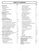
INTRODUCTION The projector is a multimedia projector designed for portability, durability, and ease of use. The projector utilizes built-in multimedia features, a palette of 16.77 million colors, and active matrix liquid crystal display (LCD) technology. COMPATIBILITY The projector is compatible with many different types of personal computers and video devices, including; ¡IBM-compatible computers, including laptops, up to 1024 x 768 resolution.
POWER REQUIREMENTS Your projector uses nominal input voltages of 100-120 VAC or 200-240 VAC. The projector automatically selects the correct input voltage. The projector is designed to work with single-phase power systems having a grounded neutral conductor. To reduce the risk of electrical shock, do not plug into any other type of power system. Consult your authorized dealer or service station if you are not sure what type of power is supplied to your building.
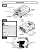
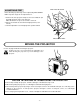
DESCRIPTION FRONT PROJECTION LENS INFRARED REMOTE RECEIVER FEET LOCK BUTTON AIR INTAKE VENT FEET LOCK BUTTON REMOVABLE LENS COVER SPEAKERS REAR INFRARED REMOTE RECEIVER EXHAUST VENT CAUTION HOT AIR ! Air blown from the exhaust vent is hot. Observe the following when handling your projector or choosing a location to install it. ¡Keep heat-sensitive objects away from the exhaust port. ¡If you set the projector on top of a metallic surface, the surface will become hot because of the hot air exhaust.
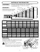
SETTING-UP THE PROJECTOR ¡This projector is basically designed to project on a flat projection surface. ¡This projector can be focused from 4.6’ (1.4 m) ~ 35.4’ (10.8 m). ¡Use the illustration below as an example when positioning 300" the projector to the screen. (762 cm) 250" Maximum Zoom ROOM LIGHT (635 cm) 200" Ideally the projector should be placed in a Minimum Zoom (508 cm) 231" room with limited light. Picture quality will (586.7 cm) 150" be directly affected by lighting conditions.
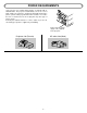
FEET LOCK BUTTONS ADJUSTABLE FEET Picture tilt and projection angle can be adjusted by ADJUSTABLE FEET. Projection angle can be adjusted 0 to 6°. 1. Lift the front of the projector and press the feet lock buttons (left and right) under the sides of the projector. When the buttons are pressed, feet lock is released. 2. Release the buttons at desired front height position. (feet is locked). 3. Turn the adjustable feet and adjust picture position and tilt.
CONNECTING THE PROJECTOR Your projector is equipped with various audio/video inputs and outputs including Computer HDB15-pin (VGA) terminals, Monitor HDB15-pin (VGA) terminals and S-VHS video. CONNECTING THE COMPUTER CONNECTING TO THE COMPUTER INPUT HDB15-PIN (VGA) TERMINALS (1 and 2) Personal computers can be connected to the HDB15-pin (VGA) terminal on the projector. ¡Connect the computer to these terminals using the VGA cable and VGA/MAC adapter (not provided).
Connecting an IBM-compatible desktop computer COMPUTER MONITOR CABLE (NOT PROVIDED) COMPUTER OUTPUT VGA CABLE (PROVIDED) AUDIO OUTPUT SERIAL PORT PS/2 INPUT PORT INPUT COMPUTER INPUT 1 or 2 MONITOR OUTPUT MOUSE CABLE FOR PS/2 PORT (PROVIDED) COMPUTER IN 1 CONTROL PORT OUTPUT 1 or 2 MOUSE CABLE FOR SERIAL PORT (NOT PROVIDED) AUDIO 1 COMPUTER IN 2 CONTROL PORT 1 (STEREO) AUDIO 2 MONITOR OUT CONTROL PORT 2 (STEREO) AV IN COMPUTER AUDIO INPUT 1 or 2 R EXT.
Connecting a Macintosh desktop computer COMPUTER MONITOR CABLE (NOT PROVIDED) VGA CABLE (PROVIDED) 123456 ON COMPUTER OUTPUT VGA/MAC ADAPTER (NOT PROVIDED) AUDIO OUTPUT COMPUTER INPUT 1 or 2 ADB PORT INPUT MOUSE CABLE FOR ADB PORT (NOT PROVIDED) MONITOR OUTPUT COMPUTER IN 1 AUDIO 1 COMPUTER IN 2 CONTROL PORT 1 (STEREO) CONTROL PORT OUTPUT 1 or 2 AUDIO CABLE (NOT PROVIDED) R CONTROL PORT 2 R EXT.
Connecting an IBM-compatible laptop computer COMPUTER COMPUTER OUTPUT AUDIO OUTPUT SERIAL PORT INPUT VGA CABLE (PROVIDED) PS/2 PORT INPUT COMPUTER INPUT 1 or 2 MOUSE CABLE FOR PS/2 PORT (PROVIDED) CONTROL PORT OUTPUT 1 or 2 COMPUTER IN 1 AUDIO 1 COMPUTER IN 2 CONTROL PORT 1 (STEREO) MOUSE CABLE FOR SERIAL PORT (NOT PROVIDED) COMPUTER AUDIO INPUT 1 or 2 AUDIO CABLE (NOT PROVIDED) R CONTROL PORT 2 EXT.
Connecting a Macintosh PowerBook computer COMPUTER The Macintosh PowerBook requires the use of the PowerBook Video Adapter shipped with the PowerBook. VGA CABLE (PROVIDED) 123456 ON TO POWERBOOK VIDEO ADAPTER VGA/MAC ADAPTER (NOT PROVIDED) COMPUTER INPUT 1 or 2 AUDIO OUTPUT ADB PORT INPUT MOUSE CABLE FOR ADB PORT (NOT PROVIDED) COMPUTER IN 1 AUDIO 1 COMPUTER IN 2 CONTROL PORT 1 (STEREO) R AUDIO Speaker (L) AUDIO MONITOR OUTPUT R (STEREO) AV IN COMPUTER AUDIO INPUT 1 or 2 EXT.
CONNECTING THE VIDEO EQUIPMENT CONNECTING TO THE AV INPUT JACKS Connect to the video and audio outputs of a VCR, video disc player, DVD player, video camera, satellite TV tuner or other AV equipment. ¡Connect audio/video outputs from external sources to the input jacks using the audio/video cable. ¡If the audio signal from the AV equipment is stereo, be sure to connect the right and left channels to the respective right and left audio input jacks.
Connecting the Video Equipment VIDEO EQUIPMENT DVD Player Video Disc Player Video Cassette Recorder L R AUDIO OUTPUT Satellite TV Tuner VIDEO OUTPUT COMPUTER IN 1 VIDEO INPUT AUDIO 1 COMPUTER IN 2 CONTROL PORT 1 (STEREO) AUDIO 2 MONITOR OUT (STEREO) AV IN R EXT. SP (8Ω) CONTROL PORT 2 (STEREO) AUDIO L S-VIDEO INPUT MONITOR OUT (MONO) VIDEO S-VIDEO R AUDIO L VIDEO AUDIO INPUT AUDIO INPUT AUDIO MONITOR OUTPUT R VIDEO MONITOR OUTPUT L Speaker (L) AUDIO INPUT Amp.
CONNECTING AN EXTERNAL SPEAKER CONNECTING TO THE EXT. SP. JACK (3.5mm mini stereo type) This jack outputs stereo speaker sound which viewing on screen. If you use external speaker system, connect stereo type external speaker jack. Internal speaker sound is disconnected when speaker jack is connected. COMPUTER IN 1 AUDIO 1 COMPUTER IN 2 CONTROL PORT 1 (STEREO) AUDIO 2 MONITOR OUT CONTROL PORT 2 (STEREO) AV IN R EXT.
OPERATION OF CONTROLS TOP OF THE PROJECTOR FRONT INDICATORS FRONT INDICATORS TOP CONTROLS w q e LAMP WARNING READY REPLACE TEMP.
q w e r t y u i o !0 !1 !2 !3 !4 LAMP REPLACEMENT INDICATOR Light is orange when projection lamp is nearing end of service life. TEMPERATURE WARNING INDICATOR Flashes red when internal projector temperature is too high. READY INDICATOR Light is green when projector lamp is ready to be turned on. LAMP POWER INDICATOR Light is dim when the projector is on. Light is brightened when the projector is in stand-by mode. LAMP POWER ON/OFF BUTTON Used to turn projection lamp on or off.
REAR OF THE PROJECTOR !5 !6 !7 COMPUTER IN 1 COMPUTER IN 2 MONITOR OUT AUDIO 1 !8 !9 @2 !5 !6 !7 !8 !9 @0 @1 CONTROL PORT 1 (STEREO) AUDIO 2 (STEREO) AV IN R EXT. SP (8Ω) CONTROL PORT 2 (STEREO) AUDIO L MONITOR OUT (MONO) @3 VIDEO @4 COMPUTER INPUT-1 TERMINAL Used to connect a computer to the projector. COMPUTER INPUT-2 TERMINAL Used to connect a computer to the projector. MONITOR OUTPUT TERMINAL Used to connect a monitor to the projector.
OPERATION OF REMOTE CONTROL This remote control unit is not only able to operate the projector but also usable as a wireless mouse for a PC. One pointing pad and two click buttons are used for wireless mouse operation. Wireless mouse is usable when PC mouse pointer is displayed on the screen. When the menu or indicator of the projector is displayed on the screen instead of the PC mouse pointer, the wireless mouse cannot be used.
q w e r t y u i o !0 !1 !2 !3 !4 MODE BUTTON Used to select source. (Computer 1, Computer 2 or Video 1 Input) LAMP POWER ON/OFF BUTTON Used to turn the projection lamp on or off. VOLUME BUTTONS Used to adjust volume. ZOOM BUTTON Used to select power zoom lens adjust. P-TIMER BUTTON Used to operate the P-TIMER function. FOCUS BUTTON Used to select focus adjust. NO SHOW BUTTON Used to change the screen into black image. SOUND MUTE BUTTON Used to mute sound. D.
REMOTE CONTROL BATTERY INSTALLATION 1 2 Remove the battery compartment lid. Slide the batteries into the compartment. 3 Replace the compartment lid. Note: For correct polarity (+ and – terminal), be sure the battery terminals are in contact with the pins in the compartment. USING THE REMOTE CONTROL UNIT Point the remote control toward the projector (Receiver window) whenever pressing the buttons. Maximum operating range for the remote control is about 16.
CONTROL THE PROJECTOR The projector has two types of operation: DIRECT OPERATION and MENU OPERATION. DIRECT OPERATION allows you to operate the projector by using one button without showing the MENU. In MENU OPERATION mode, you display menus where you can adjust the projector’s settings. Follow the instruction for each control.
MENU OPERATION ADJUST ITEM MODE SELECT TOP CONTROL OF THE PROJECTOR MENU BUTTON POINT LEFT/RIGHT BUTTONS SELECT BUTTON POINT UP/DOWN BUTTONS SELECT BUTTON REMOTE CONTROL UNIT MENU BUTTON POINT (LEFT/RIGHT) BUTTON SELECT (REAR CLICK) BUTTON POINT (UP/DOWN) BUTTON SELECT (REAR CLICK) BUTTON 1.
3.
USING THE PROJECTOR TO TURN ON THE PROJECTOR Connect the projector to a source (Computer, VCR, Video Camera, Video Disc Player, etc.) using the appropriate terminals on the rear of the projector (See “CONNECTING THE PROJECTOR” section on pages 10-17). Connect the projector’s AC power cord into a wall outlet and turn the MAIN ON/OFF switch (located on the rear of the projector) to the ON position. The LAMP POWER indicator will light RED, the READY indicator will light GREEN.
SOUND VOLUME ADJUSTMENT Press the VOLUME buttons (located on remote control unit or on the projector) to adjust the volume. The volume display will be displayed on the screen for a few seconds. Pressing volume (+) will increase volume and increase the number on the screen. Pressing volume (–) will decrease volume and decrease the number on the screen. SOUND MUTE FUNCTION Pressing the MUTE button on the remote control unit will mute audio. Press the MUTE button again to restore audio to its previous level.
MENU OPERATION In MENU OPERATION mode, you display menus where you can adjust the projector’s settings. You can use the TOP CONTROL OF THE PROJECTOR or the REMOTE CONTROL UNIT. REMOTE CONTROL UNIT TOP CONTROL OF THE PROJECTOR POINT UP BUTTON MENU BUTTON MENU MODE POINT LEFT BUTTON MODE E VOLUM MUT E POINT RIGHT BUTTON AUTO IMAGE ON-O FF ZOOM P-TIMER FOCUS NO SH D.
SOUND ADJUSTMENT You can adjust the sound volume and sound mute used in the MENU. 1. Press the MENU BUTTON and the MAIN MENU DISPLAY dialog box will appear. 2. Press the POINT LEFT/RIGHT BUTTON(s) to select SOUND and press the SELECT (REAR CLICK) BUTTON. Another dialog box SOUND ADJUST DISPLAY will appear. 3. Press the POINT DOWN BUTTON and a red arrow will appear. 4. Move the arrow to an item that you want to adjust by pressing the POINT UP/DOWN BUTTON(s). 5.
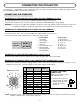
COLOR SYSTEM SELECT (VIDEO MODE) This projector is compatible with the five major broadcast video standards: PAL, SECAM, NTSC, NTSC 4.43 and PAL-M (COLOR SYSTEMs). It automatically adjusts itself to optimize its performance for the incoming video (Except PAL-M). However, if the video signal is not strong enough to detect the video format, the projector may not reproduce the proper video image. In case this happens, this projector allows you to choose a specific broadcast signal format. 1.
PICTURE IMAGE ADJUSTMENT (VIDEO MODE) Although picture adjustments have been preset at the factory, you may want to change the setting. 1. Press the MENU BUTTON and the MAIN MENU DISPLAY dialog box will appear. 2. Press the POINT LEFT/RIGHT BUTTON(s) to select IMAGE and press the SELECT (REAR CLICK) BUTTON. Another dialog box IMAGE ADJUST DISPLAY will appear. This shows the current picture settings. 3. In this dialog box, you can adjust the settings by increasing or decreasing the levels shown as numbers.
PICTURE SCREEN ADJUSTMENT (VIDEO MODE) This projector has the Wide function, which enables you to view a wider video image. WIDE function This projector is able to project not only a normal video image (with 4 x 3 aspect ratio), but also a wider video image by compressing 4 x 3 image. This feature enable you to enjoy watching pictures like cinema images. You can switch either to WIDE or to REGULAR screen mode. 1. Press the MENU BUTTON and the MAIN MENU DISPLAY dialog box will appear. 2.
COMPUTER SYSTEM SELECT (COMPUTER MODE) This projector is adjustable to different types of computer display signals based on VGA, SVGA or XGA (See “COMPATIBLE COMPUTER SPECIFICATIONS” on the next page). If you set MODE SELECT to “COMPUTER”, the projector will automatically process the incoming signal and project the proper image without any special setting. Although this will work in most cases, you may be required to manually set the projector for some computer signals.
COMPATIBLE COMPUTER SPECIFICATIONS ON-SCREEN DISPLAY RESOLUTION Horizontal Frequency (kHz) Vertical Frequency (Hz) VGA1 640 x 480 31.47 59.88 VGA2 720 x 400 31.47 70.09 VGA3 640 x 400 31.47 70.09 VGA4 640 x 480 37.86 74.38 VGA5 640 x 480 37.86 72.81 VGA6 640 x 480 37.50 75.00 VGA7 640 x 480 43.269 85.00 MAC LC13 640 x 480 34.97 66.60 MAC 13 640 x 480 35.00 66.67 SVGA1 800 x 600 35.156 56.25 SVGA2 800 x 600 37.88 60.32 SVGA3 800 x 600 46.875 75.
AUTO IMAGE ADJUSTMENT (COMPUTER MODE) The Auto image function is provided to automatically adjust Fine sync., Total dots and Screen position for most computers. 1. Press the MENU BUTTON and the MAIN MENU DISPLAY dialog box will appear. 2. Press the POINT LEFT/RIGHT BUTTON(s) to select AUTO IMAGE and press the SELECT (REAR CLICK) BUTTON. Another dialog box AUTO IMAGE SETTING DISPLAY will appear. 3. Press the POINT DOWN BUTTON and a red arrow will appear. 4.
PICTURE IMAGE ADJUSTMENT (COMPUTER MODE) Picture adjustments have been preset at the factory. If you want to change the setting, operate the projector as follows. 1. Press the MENU BUTTON and the MAIN MENU DISPLAY dialog box will appear. 2. Press the POINT LEFT/RIGHT BUTTON(s) to select IMAGE and press the SELECT (REAR CLICK) BUTTON. Another dialog box IMAGE ADJUST DISPLAY will appear. This shows the current picture settings. 3.
PICTURE POSITION ADJUSTMENT (COMPUTER MODE) 1. Press the MENU BUTTON and the MAIN MENU DISPLAY dialog box will appear. 2. Press the POINT LEFT/RIGHT BUTTON(s) to select POSITION and press the SELECT (REAR CLICK) BUTTON. Another dialog box POSITION SETTING DISPLAY will appear. 3. Press the POINT DOWN BUTTON and a red arrow will appear. 4.
PC ADJUSTMENT This projector can automatically detect most display signals from most personal computers currently distributed. However, some computers employ a special signal format which is different from the standard one and may not be detected by this projector. If this happens, the projector cannot reproduce a proper image. Instead the image is often recognized as a flickering picture, a non-synchronized picture, a non-centered picture or a skewed picture.
6. Another dialog box “PC ADJUSTMENT DISPLAY 1” will appear and the parameter data for the Mode you have selected is shown in this dialog box. 7. The parameters will be filled with the data determined by the projector according to the present signal input. 8. The function of the parameters and their values are summarized in the table below. 9. Move the arrow to an item that you want to adjust by pressing the POINT UP/DOWN BUTTON(s). 10.
17. Another dialog box “PC ADJUSTMENT DISPLAY 2” will appear and the parameter data for the Mode you have selected is shown in this dialog box. 18. Move the arrow to an item that you want to adjust by pressing the POINT UP/DOWN BUTTON(s). 19. To increase the level, point the arrow to ▲ and then press the SELECT (REAR CLICK) BUTTON. To decrease the level, point the arrow to ▼ and then press the SELECT (REAR CLICK) BUTTON. 20.
MODE FREE The Mode free function is provided to confirm or clear the parameter data produced by PC ADJUST. 1. Press the MENU BUTTON and the MAIN MENU DISPLAY dialog box will appear. 2. Press the POINT LEFT/RIGHT BUTTON(s) to select PC ADJUST and press the SELECT (REAR CLICK) BUTTON. Another dialog box “ Where to reserve” will appear. 3. Press the POINT DOWN BUTTON and a red arrow will appear. 4.
PICTURE SCREEN ADJUSTMENT (COMPUTER MODE) This projector can adjust the image size and pan the image with PICTURE SCREEN ADJUSTMENT. 1. Press MENU BUTTON and MAIN MENU DISPLAY dialog box will appear. 2. Press POINT LEFT/RIGHT BUTTON(s) to select SCREEN and press SELECT (REAR CLICK) BUTTON. Another dialog box SCREEN ADJUST DISPLAY will appear. 3. Press POINT DOWN BUTTON and a red arrow will appear. 4.
OTHER FUNCTION SETTING This projector has other function settings; Blue back, Display, Ceiling, Rear, Split wipe and Lamp age. BLUE BACK When this function is in the “On” position, the projector will project a blue image without video noise on the screen when the video source is unplugged or turned off. DISPLAY When this function is in the “On” position, on-screen displays always appear when adjustments are made.
BLUE BACK, DISPLAY, CEILING, REAR AND SPLIT WIPE 1. Press the MENU BUTTON and the MAIN MENU DISPLAY dialog box will appear. 2. Press the POINT LEFT/RIGHT BUTTON(s) to select SETTING and press the SELECT (REAR CLICK) BUTTON. Another dialog box SETTING DISPLAY will appear. 3. Press the POINT DOWN BUTTON and a red arrow will appear. 4. Move the arrow to an item you want to set by pressing the POINT UP/DOWN BUTTON(s). 5. If you want to change the setting (On or Off), press the SELECT (REAR CLICK) BUTTON. 6.
LAMP AGE NOTE: Do not reset the LAMP REPLACEMENT MONITOR TIMER, except after the lamp is replaced. 1. Press the MENU BUTTON and the MAIN MENU DISPLAY dialog box will appear. 2. Press the POINT LEFT/RIGHT BUTTON(s) to select SETTING and press the SELECT (REAR CLICK) BUTTON. Another dialog box SETTING DISPLAY will appear. 3. Press the POINT DOWN BUTTON and a red arrow will appear. 4. Move the arrow by pressing the POINT UP/DOWN BUTTON(s) to select Lamp age and then press the SELECT (REAR CLICK) BUTTON.
AIR FILTER CARE AND CLEANING The removable air filter prevents dust from accumulating on the surface of the projection lens and projection mirror. Should the air filter become clogged with dust particles, it will reduce the cooling fan’s effectiveness and may result in internal heat build up and reduce the life of the projector. To clean the air filter, follow the cleaning procedures below: 1. Turn the LAMP POWER ON/OFF button OFF. 2. Remove the air filter cover. 3.
LAMP REPLACEMENT If the lamp fails to come on and the lamp monitor on the projector light is orange, you must replace the bulb. ¡For continued safety, replace with a lamp assembly of the same type. ¡Allow the projector to cool for at least 45 minutes before you open the lamp cover. The inside of the projector can become very hot. ¡Do not drop the lamp module or touch the glass bulb ! The glass can shatter and cause injury. Follow these steps to replace the lamp assembly. 1.
CLEANING THE LENS Follow these steps to clean the projection lens: 1. Apply a non-abrasive camera lens cleaner to a soft, dry cleaning cloth. Avoid using an excessive amount of cleaner. Abrasive cleaners, solvents or other harsh chemicals might scratch the lens. 2. Lightly wipe the cleaning cloth over the lens. 3. If you don’t intend to use the projector immediately, replace the lens cover. TROUBLESHOOTING Before calling Boxlight Corporation for assistance, check the matters below once again. 1.
Try these Solutions: Problem: Picture is L/R Reversed. Check Ceiling/Rear feature. (See “OTHER FUNCTION SETTING” section on pages 44 ~ 45). Picture is T/B inverted. Check Ceiling feature. (See “OTHER FUNCTION SETTING” section on pages 44 ~ 45). Some displays are not seen during the operation. Check Display feature. (See “OTHER FUNCTION SETTING” section on pages 44 ~ 45). No sound. ¡Check audio cable connection from audio input source. ¡Adjust audio source. ¡Press the VOLUME (+) button.
TECHNICAL SPECIFICATIONS SPECIFICATIONS Projector Type Multi-media Projector Dimensions (W x H x D) 10.7” (272 mm) x 5.7” (145.5 mm) x 16.2” (412.5 mm) Net Weight 14.6 Ibs (6.6 kg) LCD Panel System 1.3” TFT Active Matrix type (Thin Film Transistor) x 3 Number of Pixels 1,440,000 {480,000 (800 x 600) x 3} Color System 5 color system (PAL, SECAM, NTSC, NTSC4.43 and PAL-M) Scanning Frequency H-sync. 15 ~ 100 KHz, V-sync.
LIMITED WARRANTY BOXLIGHT CORPORATION (“BOXLIGHT”) warrants that each Boxlight MP-25t (“the Product”) sold hereunder will conform to and function in accordance with the written specifications of BOXLIGHT. Said limited warranty shall apply only to the first person or entity that purchases the Product for personal or business use and not for the purpose of distribution resale. Said warranty shall continue for a period of two (2) years from the date of such purchase.