USER’S GUIDE BOXLIGHT CP-11t
INFORMATION TO THE USER NOTE : This equipment has been tested and found to comply with the limits for a Class A digital device, pursuant to Part 15 of FCC Rules. These limits are designed to provide reasonable protection against harmful interference when the equipment is operated in a commercial environment. This equipment generates, uses and can radiate radio frequency energy, and if not installed and used in accordance with the instruction manual, may cause harmful interference to radio communications.
IMPORTANT SAFETY INSTRUCTIONS All the safety and operating instructions should be read before the product is operated. Read all of the instructions given here and retain them for later use. Unplug this projector from AC power supply before cleaning. Do not use liquid or aerosol cleaners. Use a damp cloth for cleaning. Do not use attachments not recommended by the manufacturer as they may cause hazards. Do not place this projector on an unstable cart, stand, or table.
TABLE OF CONTENTS FEATURES AND DESIGN PREPARATION NAME OF EACH PART OF THE PROJECTOR SETTING-UP THE PROJECTOR POSITIONING THE PROJECTOR ADJUSTABLE FEET CONNECTING THE AC POWER CORD VENTILATION MOVING THE PROJECTOR CONNECTING THE PROJECTOR TERMINALS OF THE PROJECTOR CONNECTING TO THE VIDEO EQUIPMENT CONNECTING TO THE COMPUTER BEFORE OPERATION 5 6 6 7 7 7 8 8 9 10 10 11 12 14 OPERATION OF THE REMOTE CONTROL 14 LASER POINTER FUNCTION REMOTE CONTROL BATTERIES INSTALLATION 14 15 TOP CONTROLS AND INDICA
FEATURES AND DESIGN This Multimedia Projector is designed with the most advanced technology for portability, durability, and ease of use. The projector utilizes built-in multimedia features, a palette of 16.77 million colors, and matrix liquid crystal display (LCD) technology. ◆ Compatibility This projector is compatible with many different types of personal computers and video devices, including; ● IBM-compatible computers, including laptops, up to 1024 x 768 resolution.
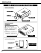
PREPARATION NAME OF EACH PART OF THE PROJECTOR FRONT OF THE CABINET PROJECTION LENS LENS COVER CARRY HANDLE INFRARED REMOTE RECEIVER SPEAKER (Monaural) BACK OF THE CABINET EXHAUST VENT HOT AIR EXHAUSTED ! Air blown from the exhaust vent is hot. When using or installing the projector, following attention should be taken. ● Do not put a flammable object near this vent. ● Keep heat-sensitive objects away from the exhaust vent. ● Do not touch this area especially screws and metallic parts.
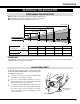
PREPARATION SETTING-UP THE PROJECTOR POSITIONING THE PROJECTOR ● This projector is designed to project on a flat projection surface. ● The projector can be focused from 4.6’(1.4m) ~ 35.4’(10.8m). ● Refer to the figure below to adjust the screen size. 35.4’ (10.8m) 24.0’ (7.3m) 300” 18.0’ (5.5m) 200” 11.8’ (3.6m) 150” 4.6’ (1.
PREPARATION CONNECTING THE AC POWER CORD This projector uses nominal input voltages of 100-120 V AC or 200-240 V AC. The projector automatically selects the correct input voltage. It is designed to work with single-phase power systems having a grounded neutral conductor. To reduce the risk of electrical shock, do not plug into any other type of power system. Consult your authorized dealer or service station if you are not sure of the type of power supply being in use.
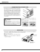
PREPARATION MOVING THE PROJECTOR Use the Carry Handle when moving the Projector. When moving the projector, replace the lens cover and retract feet to prevent damage to the lens and cabinet. When this projector is not in use for an extended period, replace the lens cover, retract the Adjustable Feet and apply the dust cover supplied with this projector. CAUTION WHEN CARRYING OR TRANSPORTING THE PROJECTOR ● Do not drop or bump the projector, otherwise damages or malfunctions may result.
CONNECTING THE PROJECTOR TERMINALS OF THE PROJECTOR S-VIDEO INPUT JACK VIDEO INPUT JACK Connect the S-VIDEO output from the video equipment to this terminal. (Refer to P11.) Connect the video output from the video equipment to this terminal. (Refer to P11.) S-VIDEO AUDIO INPUT JACKS Connect the audio outputs from the video equipment to these terminals. (Refer to P11.) ● When the audio output is monaural, connect it to the Left jack.
CONNECTING THE PROJECTOR CONNECTING TO THE VIDEO EQUIPMENT Video Source (example) Video Cassette Recorder Used cables for connection Video Disc Player Video / Audio Output S-VIDEO Output • VIDEO CABLE ✽ • S-VIDEO CABLE ✽ • AUDIO CABLE (stereo) ✽ ✽ These cables are not supplied with this projector. Video Audio Cable ✽ S-VIDEO Cable ✽ Use either the VIDEO jack or S-VIDEO jack. When the both jacks are connected, the S-VIDEO jack has priority over the VIDEO jack.
CONNECTING THE PROJECTOR CONNECTING TO THE COMPUTER To connect to the computer, refer to the figure below. Used cables for connection • VGA CABLE • CONTROL CABLE FOR PS/2 PORT • CONTROL CABLE FOR SERIAL PORT,or ADB PORT ✽ • MAC ADAPTER ✽ • MONITOR CABLE ✽ • PC AUDIO CABLE (stereo) ✽ ✽ These cables are not supplied with this projector.
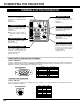
CONNECTING THE PROJECTOR S-VIDEO R-AUDIO-L(MONO) VIDEO AUDIO IN OUT COMPUTER IN MONITOR OUT CONTROL PORT COMPUTER IN MONITOR OUT CONTROL PORT AUDIO IN AUDIO OUT ◆ MAC ADAPTER (Not supplied) Use one of these Control Cables corresponding with the terminal of your computer. Set the switches as shown in the table below depend- ON ing on the RESOLUTION MODE that you want to use before your turn on the OFF projector and computer.
BEFORE OPERATION OPERATION OF THE REMOTE CONTROL Left Side POWER ON-OFF BUTTON COMPUTER BUTTON ON Used to select COMPUTER output source. (P22) ON-OFF COMPUTER VIDEO ZOOM FOCUS VOLUME Used to turn the projector on or off. (P19) VIDEO BUTTON F ALL OF LOCK Used to select VIDEO source. (P29) MUTE D.ZOOM POINT BUTTON MENU BUTTON Used to move the pointer on the MENU, to adjust the item, or to pan the image in DIGITAL ZOOM mode. (P28) It is also used as a PC mouse in Wireless Mouse Operation.
BEFORE OPERATION Operating Range ON-OFF COMPUTER VIDEO ZOOM BUTTON FOCUS BUTTON ZOOM FOCUS VOLUME LOCK Used to adjust zoom. (P20) VOLUME BUTTON Used to adjust volume. (P21) MUTE D.ZOOM Point the remote control toward the projector (the Remote Receiver) whenever pressing the buttons. Maximum operating range for the remote control is about 16.4’ (5m) and 60° front and rear of the projector D.ZOOM BUTTON Used to adjust focus.
BEFORE OPERATION TOP CONTROLS AND INDICATORS ZOOM BUTTONS Used to select zoom adjust. (P20) POWER ON–OFF BUTTON FOCUS BUTTONS Used to turn the projector on or off. (P19) Used to select focus adjust. (P20) ZOOM LAMP INDICATOR This indicator is dim when the projector is turned on. And bright when the projector is in stand-by mode. FOCUS VOLUME VOLUME BUTTONS Used to adjust volume.
BEFORE OPERATION OPERATING ON-SCREEN MENU HOW TO OPERATE ON-SCREEN MENU You can control and adjust this projector through the ON-SCREEN MENU. Refer to the following pages to operate each adjustment on the ON-SCREEN MENU. WIRELESS REMOTE CONTROL POINT BUTTON Used to move the Pointer UP/ DOWN/ RIGHT/ LEFT. 1 MOVING THE POINTER Move the pointer (see the NOTE below) by pressing POINT button(s) on the TOP CONTROL or the REMOTE CONTROL. 2 SELECT THE ITEM Select the item by pressing SELECT button.
BEFORE OPERATION MENU BAR MENU BAR IN COMPUTER MODE MODE MENU Used to select the Computer input mode. (Refer to P22) Press MENU BUTTON while in Computer mode. AUTO IMAGE MENU PC ADJUST MENU SETTING MENU Used to adjust Fine sync., Total dots, and Picture Position automatically. (Refer to P27) Used to adjust the parameters to match with the input signal format. (Refer to P24, 25) Used to set the Display Menu and to reset Lamp Replacement Monitor Timer.
BASIC OPERATION TURNING ON / OFF THE PROJECTOR TURNING ON THE PROJECTOR 1 Complete the peripheral connections (with Computer, VCR, etc.) before turning on the projector. (Refer to "CONNECTING TO THE PROJECTOR" on Pages 10~13 for connecting that equipment.) 2 Connect the projector's AC power cord into a wall outlet. The LAMP indicator lights RED, and the READY indicator lights GREEN. 3 Press the power ON-OFF button on the Remote Control Unit or on the Top Control to ON.
BASIC OPERATION ADJUSTING THE IMAGE ZOOM ADJUSTMENT 1 Press the ZOOM ▲/▼ button(s) on the Top Control or on the Remote Control Unit to turn on the ZOOM mode. 2 Press the ZOOM ▲ button to make the image larger, and press the ZOOM ▼ button to make the image smaller. Zoom In the Computer mode, the image can be expanded, compressed, and panned with the Digital Zoom function. Refer to page 28 for the Digital Zoom operation. The message disappears after 4 seconds.
BASIC OPERATION NO SHOW FUNCTION Press the NO SHOW button on the Remote Control Unit to black out the image. This function is cancelled when the NO SHOW button is pressed again or any other function button is pressed. No show The message disappears after 4 seconds. PICTURE FREEZE FUNCTION Press the FREEZE button on the Remote Control Unit to freeze the picture on-screen. This function is cancelled when the FREEZE button is pressed again or any other function button is pressed.
COMPUTER MODE SELECTING COMPUTER MODE DIRECT OPERATION Select COMPUTER mode by pressing the MODE button on the Top Control or the COMPUTER button on the Remote Control Unit. MODE button COMPUTER VIDEO MENU OPERATION Press the MENU button and the ON-SCREEN MENU will appear. Press the POINT LEFT/RIGHT buttons to select Computer and press the SELECT button. CURRENT MODE DISPLAY When selecting the Computer Mode, the Current Mode display appears. It shows the information of the computer of the mode selected.
COMPUTER MODE COMPATIBLE COMPUTER SPECIFICATIONS Basically this projector can accept the signal from all computers with the V, H-Frequency mentioned below and less than 135 MHz of Dot Clock. V-Freq. (Hz) 59.88 ON-SCREEN DISPLAY RESOLUTION 640 x 480 H-Freq. (kHz) 31.47 800 x 600 H-Freq. (kHz) 47.90 V-Freq. (Hz) 71.92 SVGA 10 VGA 2 720 x 400 31.47 70.09 SVGA 11 800 x 600 32.70 51.09 VGA 3 640 x 400 31.47 70.09 SVGA 12 800 x 600 38.00 60.51 VGA 4 640 x 480 37.86 74.
COMPUTER MODE PC ADJUSTMENT This Projector can automatically tune to the display signals from most personal computers currently distributed. However, some computers employ the special signal formats which are different from the standard ones and may not be tuned by Multiscanning of this projector. If this happens, the projector cannot reproduce a proper image and the image is recognized as a flickering picture, a non-synchronized picture, a non-centered picture or a skewed picture.
Total lines The number of the total vertical lines. Adjust the number to match the image of your personal computer. Total dots The number of the total dots in one horizontal period. Adjust the number to match the image of your personal computer. Horizontal / Vertical Adjustment of the horizontal or vertical picture position. When the image is not centered on the screen, adjust each of those items. Clamp Adjustment of the clamp level. When the image has a dark bar(s), try this adjustment.
COMPUTER MODE ADJUST PICTURE IMAGE MANUALLY 1 Press the MENU button and the ON-SCREEN MENU will appear. Press the POINT LEFT/RIGHT buttons to select IMAGE and press the SELECT button. Another dialog box PICTURE IMAGE ADJUSTMENT Menu will appear. 2 Press the POINT DOWN button and a red-arrow icon will appear. Move the arrow to the item that you want to change by pressing the POINT UP/DOWN buttons. To change the value, press either the POINT RIGHT button or the POINT LEFT button.
COMPUTER MODE AUTO IMAGE FUNCTION The Auto Image function is provided to automatically adjust Fine sync., Total dots, and Picture Position for most computers. 1 Press the MENU button and the ON-SCREEN MENU will appear. Press the POINT LEFT/RIGHT buttons to select AUTO IMAGE and press the SELECT button. Another dialog box AUTO IMAGE Menu will appear. 2 Move the arrow to an item that you want to adjust by pressing the POINT UP/DOWN button. Change the setting On or Off by pressing the SELECT button.
COMPUTER MODE PICTURE SCREEN ADJUSTMENT This projector has a picture screen resize function, which enables you to display the desirable image size. 1 Press the MENU button and the ON-SCREEN MENU will appear. Press the POINT LEFT/RIGHT buttons to select SCREEN and press the SELECT button. Another dialog box PICTURE SCREEN Menu will appear. 2 Press the POINT DOWN button and a red-arrow icon will appear. Move the arrow to the function that you want to select and then press SELECT button.
VIDEO MODE SELECTING VIDEO MODE DIRECT OPERATION MODE button Select VIDEO mode by pressing the MODE button on the Top Control or the VIDEO button on the Remote Control Unit. COMPUTER VIDEO MENU OPERATION Press the MENU button and the ON-SCREEN MENU will appear. Press the POINT LEFT/RIGHT buttons to select Video and press the SELECT button. SELECTING COLOR SYSTEM 1 Press the MENU button and the ON-SCREEN MENU will appear. Press the POINT LEFT/RIGHT buttons to select SYSTEM and press the SELECT button.
VIDEO MODE PICTURE IMAGE ADJUSTMENT ADJUSTING THE PICTURE IMAGE 1 Press the MENU button and the ON-SCREEN MENU will appear. Press the POINT LEFT/RIGHT buttons to select IMAGE and press the SELECT button. Another dialog box PICTURE IMAGE ADJUSTMENT Menu will appear. 2 Press the POINT DOWN button and a red-arrow icon will appear. Move the arrow to the item that you want to adjust by pressing the POINT UP/DOWN buttons. To change the value, press either the POINT RIGHT button or the POINT LEFT button.
SETTING SETTING MENU 1 Press the MENU button and the ON-SCREEN MENU will appear. Press the POINT LEFT/RIGHT buttons to select SETTING and press the SELECT button. Another dialog box SETTING Menu will appear. 2 Press the POINT DOWN button and a red-arrow icon will appear. Move the arrow to the item that you want to set, and then press the SELECT button to set it "On" or "Off".
APPENDIX OPERATING WIRELESS MOUSE The Wireless Remote Control Unit is not only able to operate the projector but also usable as a wireless mouse for most Personal Computers. The POINT buttons and the two CLICK buttons are used for the wireless mouse operation. The wireless mouse is available only when PC mouse pointer is displayed on the screen. When the menu or the indicator of the projector is displayed on the screen instead of the PC mouse pointer, the wireless mouse cannot be used.
APPENDIX MAINTENANCE TEMPERATURE WARNING INDICATOR The TEMPERATURE WARNING Indicator flashes red when the internal temperature of the projector exceeds the normal temperature. The Indicator stops flashing when the temperature of the projector become normal. When the TEMPERATURE WARNING Indicator continues to flash, check the item listed below. 1 2 3 The Ventilation slots of the projector may be blocked. In such an event, reposition the appliance so that the ventilation slots are not obstructed.
APPENDIX LAMP REPLACEMENT INDICATOR When the life of the Lamp of this projector draws to an end, the LAMP REPLACEMENT indicator lights yellow. When the image becomes dark or the color of the image becomes unnatural, replacement of the Lamp is required. LAMP REPLACEMENT CAUTION ● For continued safety, replace with a lamp assembly of the same type. ● Allow the projector to cool for at least 45 minutes before you open the lamp cover. The inside of the projector can become very hot.
APPENDIX TROUBLESHOOTING Before calling your dealer or service station for assistance, check the matters below once again. 1. Make sure you have connected the projector to your equipment as described in the section "CONNECTING THE PROJECTOR" on pages 10 ~ 13. 2. Check cable connection. Verify that all computer, video and power cord are properly connected. 3. Verify that all power is switched on. 4. If the projector still does not produce the image, re-start the computer. 5.
APPENDIX Problem: Try these Solution Remote Control Unit does not work. ● Check the batteries. ● Check the ALL-OFF switch on the Remote Control Unit is set to “ON.”. ● Make sure nothing is between the Remote Receiver and the Remote Control Unit. ● Make sure you are not too far from the projector when using the Remote Control Unit. Maximum operating range is 16.4’ (5m). Wireless Mouse function does not work. ● Check the cable connection between the projector and the computer.
TECHNICAL SPECIFICATIONS Projector Type Dimensions (W x H x D) Net Weight LCD Panel System Panel Resolution Number of Pixels Color System Scanning Frequency Projection Image size (Diagonal) Horizontal Resolution Projection Lens Throw Distance Projection Lamp AV Input Jacks Computer Input Jacks Control Port Jack Monitor Output Jack Computer Audio Input Jack Audio Output Jack Internal Audio Amp Built-in Speaker Feet Adjustment Voltage Power Consumption Operating Temperature Storage Temperature Remote Control
LIMITED WARRANTY BOXLIGHT CORPORATION (“BOXLIGHT”) warrants that each Boxlight CP-11t (“the Product”) sold hereunder will conform to and function in accordance with the written specifications of BOXLIGHT. Said limited warranty shall apply only to the first person or entity that purchases the Product for personal or business use and not for the purpose of distribution resale. Said warranty shall continue for a period of two (2) years from the date of such purchase.