BY-WM4 PRO Dual-Channel Digital Wireless Microphone
Instruction Manual Thank you for purchasing BOYA BY-WM4 PRO system! Designed for videographers on a limited budgetand video hobbyists, BY-WM4 PRO is a new generation 2.4GHz wireless microphone system, dual-Channel for capturing audio with dual subjects to your smartphones, tablets, DSLR cameras, consumer camcorders, PCs etc. The BY-WM4 PRO system is suitable for a wide range of wireless applications such as interviews, mobile journalisms, reporting, vloggings, podcasts and more.
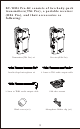
BY-WM4 Pro consists of one body-pack transmitter(TX4 Pro), a portable receiver (RX4 Pro), and their accessories as following: Transmitter(TX4 Pro) Receiver(RX4 Pro) Lavalier/lapel microphone 3.5mm to TRS audio output cable 3.
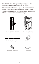
BY-WM4 Pro-K2 consists of two body-pack transmitters(TX4 Pro), a portable receiver (RX4 Pro), and their accessories as following: Transmitter(TX4 Pro) x2 Receiver(RX4 Pro) Lavalier/lapel microphone x2 3.5mm to TRS audio output cable 3.
BY-WM4 Pro-K3 is specially designed for Lightning iOS Devices.
BY-WM4 Pro-K4 is specially designed for Lightning iOS Devices.
BY-WM4 Pro-K5 specially designed for Andriod and other Type-C devices.
BY-WM4 Pro-K6 specially designed for Andriod and other Type-C devices.
Transmitter (TX4 Pro) ① ② ③ ⑧ ④ ⑤ ⑥ ⑦ 1. Microphone input - Connect the supplied lavalier microphone here. - Fully insert the microphone’s 3.5mm plug and make sure it clicks into place. 2. Line In 3. Power LED 1) The power LED flash blue when the unit is on. 2) The power LED glows red when low power.
For more details about LED indicator, please refer to as following: Status Receiver The transmitter and the receiver connects. Stays blue The transmitter and the receiver disconnects. Flashes continually Flashes continually every 1 second. every 1 second. Receiver unit is turned OFF(Transmitter is still ON) Off Transmitter unit is turned OFF(Receiver is still ON) Flashes in blue Low power Transmitter Flashes continually every 2.5 seconds. Flashes in blue Off Flashes in red 4. Power OFF/ON 5.
Receiver (RX4 Pro) ① ② ⑨ ③ ⑧ ④ ⑤ ⑥ ⑦ 1. Earphone Jack (3.5mm diameter stereo mini jack) To monitor the receiver output, connect the headphones to this connector. NOTE: Do not connect headphones with a monaural mini jack. This may lead to short-circuiting of the headphone output, resulting in distorted sound output. 2. LINE OUT (audio output) Jack - For using smartphone, tablet or Mac Connect one end (90° plug) of the supplied TRRS stereo 3.
- For cameras, camcorders, audio recorders and other audio/Video recording devices. Connect one end of the supplied TRS stereo 3.5mm mini output cable here, and the other end to camera. 3. Power LED For more details, please see “Power LED” on page 7. 4. Power OFF/ON 5. Volume +/Press these buttons to set the attenuation level of the input signal. 6. Antenna Please don’t touch here during using, otherwise, it will effect signal. 7. Battery compartment Accommodates two pieces of AAA batteries.
What’s difference? 1 3.5 mm TRRS connector - For Smartphone, tablet, Mac or laptop with combo headphone/Mic jack Connect to Receiver “LINE OUT” Connect to Smartphone SMARTPHONE MICROPHONE 2 3.5 mm TRS connector - For cameras, camcorders, audio recorders and other audio/video recording devices.
How to use it Installing batteries 1. Both transmitter and receiver requires two AAA size batteries. 2. Slide and remove the transmitter’s battery compartment cover. 3. Insert two pieces of batteries. 4. Close the battery compartment cover. 5. Do the same ways as step 2 to 4 to insert battery into receiver.
Connecting the transmitter and receiver Using the microphone with smartphone, tablet, Mac or laptop with combo headphone/Mic jack. Receiver 1. Mount receiver to Smartphone, tablet, Mac or laptop. 2. Using TRRS cable, plug the 3.5 mm connector(straight plug) into the audio jack of your smartphone. 3. Insert the 90° plug of the connecting cable into the receiver “LINE OUT” jack. 4. Insert earphone into receiver “ ” for monitoring Sound if you need. 5.
How to connect transmitter and receiver? Before leaving factory, the connection of transmitters and receiver will be established. If transmitters and receiver disconnect, please follow below steps: 1. Turn on the receiver and the transmitters. 2. Press the button “+” and “-“ for 3 seconds for receiver and press "Pair" of one transmitter for 3 seconds at the same time. 3. When transmitter and receiver connects, the light of receiver will stay blue, the light of transmitters will flash every 2.5 seconds. 4.
Using the microphone with cameras, camcorders, audio recorders and other audio/video recording devices. Receiver 1. Mount receiver to cameras, camcorders, audio recorders and other audio/video recording devices. 2. Using TRS cable, plug the 3.5 mm connector into the audio jack of your camera. 3. Insert the other end of the connecting cable into the receiver “LINE OUT” jack. 4. Insert earphone into receiver “ ” for monitoring Sound if you need. 5.
Installing or uninstalling clip 1. Clip is mounted on the microphone before leaving factory. 2. Both transmitter and receiver include clip, that means you can mount them in any place you want. 3. Adjust the direction of the microphone to your mouth by rotating the Microphone. If receiver need to be mounted onto camera hot/cold shoe, please follow below steps: 1. Push the clip to right side.
2. Push the cold shoe mount on the position. 3.
BY-WM4 PRO RXD 2.
Receiver (BY-WM4 PRO RXD) ③ ② ⑤ ④ ⑥ ① ⑦ 1. Headphone Jack (3.5mm diameter stereo mini jack) To monitor the receiver output, connect the headphones to this connector. NOTE: Do not connect headphones with a monaural mini jack. This may lead to short-circuiting of the headphone output, resulting in distorted sound output.
2. Power LED For more details about LED indicator, please refer to as following: Status Receiver Transmitter The transmitter and the receiver connects. The indicator won't light up until you turn on the audio/video app. Flashes continually every 2.5 seconds. The transmitter and the receiver disconnects. Flashes continually Flashes continually every 1 second. every 1 second.
Set Up Guide 1. Plug the BY-WM4 PRORXD directly into the lightning port of smartphone. 2. Open the audio/video app on mobile device, then the indicator of receiver should be light up. 3. The Power LED flashes slowly waiting for connecting with the transmitter.
Connecting the transmitter and the Receiver Before leaving factory, the connection of transmitters and receiver will be established. If transmitters and receiver disconnect, please follow below steps: 1.Turn on the transmitter and plug the receiver into smartphone. 2. Long press the pair bottom of receiver with pair pin, the indicator of receiver will flash quickly when entering paring mode. 3.Long press the pair button on the side of the transmitter entering the pairing mode. 4.
BY-WM4 PRO RXU 2.
Receiver (BY-WM4 PRO RXU) ③ ② ⑤ ④ ⑥ ① ⑦ 1. Headphone Jack (3.5mm diameter stereo mini jack) To monitor the receiver output, connect the headphones to this connector. NOTE: Do not connect headphones with a monaural mini jack. This may lead to short-circuiting of the headphone output, resulting in distorted sound output.
2. Power LED For more details about LED indicator, please refer to as following: Status The transmitter and the receiver connects. The transmitter and the receiver disconnects. Receiver Transmitter Stays blue Flashes continually every 2.5 seconds. Flashes continually Flashes continually every 1 second. every 1 second.
Set Up Guide 1. Plug the BY-WM4 PRO RXU directly into the lightning port of smartphone. 2. The Power LED flashes slowly waiting for connecting with the transmitter.
Connecting the transmitter and the Receiver Before leaving factory, the connection of transmitters and receiver will be established. If transmitters and receiver disconnect, please follow below steps: 1.Turn on the transmitter and plug the receiver into smartphone. 2. Long press the pair bottom of receiver with pair pin, the indicator of receiver will flash quickly when entering paring mode. 3.Long press the pair button on the side of the transmitter entering the pairing mode. 4.
Troubleshooting If you have any problem using the BY-WM4 Pro components, use the following checklist. If any problem persist, please consult our local dealer, or contact us directly. Status Cause Measure The batteries of BY-WM4 PRO TX exhausted. The units does not turn on. The Power LED of BY-WM4 PRO Open the audio/video app on mobile device, then the indicator RXD doesn’t light up while connecting with the iOS devices. of receiver should be light up.
Status Cause Measure RF interference The audio is noisy or distorted. This can include dropouts, white noise, bursts, pops and clicks. RF signal is weak. There can be a lot of RF interference outdoors. Try moving indoors, where there is less RF interference. Overhead telephone lines, fluorescent lighting, and metal fences can all cause interference. Turn off all nearby computers and mobile phones. Make sure there is an unobstructed line of sight between the transmitter and the receiver.
Specifications: BY-WM4 Pro System RF Modulation: GFSK (Gauss frequency Shift Keying) Frequency band: 2.4 GHz (2405-2478MHz) Frequency response: 35Hz-14KHz±3dB Signal/Noise: 84dB or more Distortion: 0.05% or less (32Ω,1 KHz,65mW output) RF output level: 3mW Earphone output level: 32Ω,65mW Reception sensitivity: -90dB +/- 3dB / 0dB=1V/Pa, 1kHz Audio input connector: 3.
CAUTION 1.Please use our original audio signal cable which is equipped, it’s more compatible with the wireless microphone, and make the sound better. 2.The figure given is only the approximate value that applies when there are no obstructions between the transmitter and receiver. This distance will vary depending on metal objects, people and other obstructions and on the signal strength. 3.Battery life may vary depending on the type of battery used.
MAINTENANCE • Do not operate the device with wet hands or feet. • Clean the equipment only in the way described in the instructions for use. • Take care to prevent the equipment from dropping down.Make sure that the device is properly fastened and reliably mounted. If the device has dropped down on the floor have it inspected by a skilled electrician before you switch it on again.
Warning: Changes or modifications not expressly approved by the party responsible for compliance could void the user's authority to operate the equipment. NOTE: This equipment has been tested and found to comply with the limits for a Class B digital device, pursuant to Part 15 of the FCC Rules. These limits are designed to provide reasonable protection against harmful interference in a residential installation.