BOILER INSTALLATION, OPERATION INSTRUCTIONS Savio PLUS COMBI WALL HUNG GAS BOILER FOR CENTRAL HEATING SUPPLY Please Read Instructions Carefully Save for Future Reference WARNING: If the information in this manual is not followed exactly, a re or explosion may result causing property damage, personal injury or loss of life. — Do not store or use gasoline or other ammable vapors and liquids in the vicinity of this or any other appliance. — WHAT TO DO IF YOU SMELL GAS • Do not try to light any appliance.
Dear Customer: Thank you for buying a SAVIO Plus Combi. The SAVIO Plus Combi is a high efficiency condensing, wall mounted gas boiler which provides central heat supply water. We realize that it is not possible to answer all questions about the SAVIO Plus Combi system in this manual. Reading this installation manual does not make the reader an expert in all aspects of installation and operation, and does not replace the need for a qualified, licensed heating contractor.
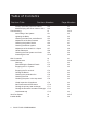
Table of Contents Section Title Section Number Warnings Important Information General Information Technical Information (M135.
Table of Contents Section Title Section Number Primary-Secondary with Zone Valves Manifold Piping with Zone Valves or Circ. Commissioning Initial Filling of the System Lightning the Boiler Checking the Gas Pres. at the Burner Adjustment of the Gas Pressure Checking the Ignition Device Checking the Burner Ignition Adjustment of the Useful c.h. Output Labels Placement Checking the Flue System and Comb.
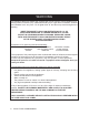
WARNING Boiler is certified as an indoor appliance. Do not install boiler outdoors or locate where it will be exposed to freezing temperatures. WARNING: If the information in this manual is not followed exactly, a re or explosion may result causing property damage, personal injury or loss of life. — Do not store or use gasoline or other ammable vapors and liquids in the vicinity of this or any other appliance. — WHAT TO DO IF YOU SMELL GAS • Do not try to light any appliance.
WARNING Any appliance that burns natural gas, propane gas, fuel oil, wood or coal is capable of producing carbon monoxide (CO). Carbon Monoxide (CO) is a gas which is odorless, colorless and tasteless but is very toxic. CO is lighter than air and thus may travel throughout the building. BRIEF EXPOSURE TO HIGH CONCENTRATIONS OF CO, OR PROLONGED EXPOSURE TO LESSER AMOUNTS OF CO MAY RESULT IN CARBON MONOXIDE POISONING.
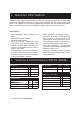
IMPORTANT INFORMATION Please read this page carefully. • ALL BOILERS MUST BE INSTALLED IN ACCORDANCE WITH NATIONAL, STATE AND LOCAL PLUMBING, HEATING AND ELECTRICAL CODES AND ORDINANCES, AS WELL AS THE REGULATIONS OF THE SERVING ELECTRICAL, WATER AND GAS UTILITIES. • All systems should be designed by competent contractors, and only persons knowledgeable in the layout and installation of heating systems should attempt the installation of any boiler.
1. General Information The SAVIO Plus Combi is a high efficiency condensing, wall mounted gas boiler which provides central heat. The boiler features a gas valve which modulates the energy input from 49,476 BTU/h to 116,008 BTU/h. The boiler is shipped fully assembled with the components listed on page 10. All units are pressure and combustion tested at the factory prior to shipping. Key Features: • Wall mountable - saving valuable floor space.
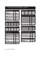
2. Technical Information Cont. ENERGY CAPACITY Nominal heat input (0/2000ft) Nominal heat input (2000/4500ft) Minimum heat input Maximum useful output (0/2000ft) Maximum useful output (2000/4500ft) Minimum useful output GAS FLOW RATE MBH 116.0 MBH 110.2 MBH 49.5 MBH 102.0 MBH 97.2 MBH 41.6 GAS SUPPLY PRESSURE Gas Min Max Natural ft³/h 48.7 115.1 Propane lb/h 2.2 5.
3. Parts List Primary Components: 1 Pump 2. Pump vent plug 3. Automatic air purger valve 4. Modulation gas valve 5. Flame-detecting electrode 6. Ignition electrodes 7. Burner 8. Combustion chamber 9. Primary heat exchanger 10. Fan 11. Air pressure switch 12. Air switch pres. Test points 13. Safety thermostat 14. Modulation operator 15. Gas valve outlet pres. Test point 16. Gas valve inlet pres. Test point 17. Central heating expansion vessel 18. Central heating temp. Probe NTC 19.
4. Internal Piping & Parts List 26 35 25 34 19 11 24 10 9 28 5 36 7 6 3 1 15 4 18 14 39 16 20 17 23 38 33 37 31 22 40 21 41 29 30 32 Note: Pressure Relief Valve (#19) should be piped to a drain or to the floor as lose as possible to a drain.
Safety thermostat 5.
5. Electric Diagrams Cont. 5.
6. Installation Location The installation location chosen must: • Comply with all clearances listed below. • Provide suitable location for the exhaust and intake venting. • Not be installed in an unheated space. • Comply with all local codes and standards. Note: Dimensions shown are minimums. Greater clearances will simplify installation and service. 15.2 in 10.0 i n 3.0 in 2.0 i n CLOSET INSTALLA TION 2.0 i n MINIMU M PER MANAN T CLEARANCE 31.6 in 1 8 . 0 in 8 .0 in CLOSET INSTALLA TION 1 5 .
7. Exhaust Pipe Location CAUTION EXTERNAL VENT SURFACES ARE HOT. IT IS RESPONSABILITY OF THE HOMEOWNER TO KEEP THE VENT TERMINAL CLEAR OF SNOW AND ICE NOTE: USE ONLY LISTED COMPONENTS SUPPLIED WITH THE BOILER. SURFACE DISCOLORATION OF THE BUILDING MAY OCCUR DUE TO IMPROPER INSTALLATION. QHT WILL NOT ACCEPT RESPONSIBILITY OR LIABILITY FOR SUCH DISCOLORATION. The Exhaust Hood must be installed on the leeward side of house and conform to the following guidelines: 1.
8. Mounting Bracket After a suitable installation location is chosen, verify that the mounting wall is properly braced and strong enough to support the 110 pound weight of the unit when lled with water. NOTE: The boiler shall be installed such that the gas ignition system components are protected from water and liquids in general (dripping,spraying, rain, etc) during the appliance operation and service. Use the paper template provided with the boiler to determine the location of the mounting bracket.
9. Venting The SAVIO Plus Combi is a mechanical draft, side wall vented boiler. There are two side wall flue options available – separate and coaxial. The coaxial option has one configuration shown on the next page. The separate option has two possible configurations shown on the following pages. There is also a vertical roof venting option. Regardless of what vent kit is installed, they should all conform to the Provisions for combustion and ventilation air in accordance with section 5.
9. Venting Cont.
9. Venting Cont. 9.3 Choice of ue: The following flue kits are available for connecting to the boiler: A Standard coaxial horizontal ue kit (Exhaust & intake outside) Figure 9.3 (Coaxial 2.4/4.0 inches – nominal lenght 3.3 ft) It can be fitted to allow discharge to the rear or either side of the boiler via the flanged boiler adapter elbow. Minimum lenght required is 2.9 ft. Maximum equivalent lenght of 8.8 ft can be achieved utilising extensions.
9. Venting Cont. B Standard separate horizontal ue kit (Exhaust & intake outside) Figure 9.4 (Twin pipe Ø 3.25 in) Various twin (split) pipes kits and optional accessories (elbows) are available to assist in the termination of the flue where the boiler is installed in a location remote to an outside wall. These kits allow for separation of the air supply pipe from the pipe that discharges the exhaust gasses.
9. Venting Cont. C Alternative separate kit (Exhaust outside & intake inside) Figure 9.5 (Twin Pipe Ø 3.25 in) This configuration of the twin pipe kit allows to discharge the exhaust gasses outside. The air supply is obtained with an air intake pipe. This allows to take air from the room where the boiler is installed. If either an additional 45° or 90° accessory elbow is used then the maximum permissible lenght of either pipe must be reduced by 3.0 ft or 5.4 ft respectively.
9. Venting Cont. D Alternative separate kit (Exhaust outside & intake inside) Figure 9.6 (Twin Pipe Ø 3.25 in) This configuration of the twin pipe kit allows to discharge the exhaust gasses outside. The air supply is obtained with an air intake pipe. This allows to take air from the room where the boiler is installed. If either an additional 45° or 90° accessory elbow is used then the maximum permissible lenght of either pipe must be reduced by 3.0 ft or 5.4 ft respectively.
9. Venting Cont. E Alternative separate kit (Exhaust & intake outside) Figure 9.7 (Twin Pipe Ø 3.25 in) These kits allow for separation of the air supply pipe from the pipe that discharges the exhaust gasses. Consequently it is possible to extend the flue system to a greater distance than that provided by the standard coaxial horizontal flue. If either an additional 45° or 90° accessory elbow is used then the maximum permissible lenght of either pipe must be reduced by 3.0 ft or 5.4 ft respectively.
9. Venting Cont. F Standard Vertical-roof kit (Exhaust & intake outside) Figure 9.8 (vertical pipe Ø 3.1 / Ø 4.9 in) This kit allows vertical termination of the flue pipe through the roof. The kit is 1.2 min length. Extension pieces (Co--axial) are also available which allows the flue system to be extended to a total overall maximum permissible length. Optional 45° and 90° elbows can be used to offset the flue route.
10. Pipe Connections The SAVIO Plus Combi is supplied with a 3/4” stainless steel gas pipe (A in figure 10.1), 2 3/4” copper pipe (C,D in figure 10.1), 2 - 1/2” (F,G in figure 10.1) located in a plastic bag in the boiler package. A) B) C) D) E) Stainless steel gas pipe Main circuit drain cock C.h. supply copper pipe C.h. return copper pipe C.h. PRV discharge copper pipe F) Dhw outlet pipe G) Dhw inlet pipe H) Condensate trap Figure 10.
11. Gas Pipe Connections Gas supply piping is to be sized and installed properly in order to provide a supply of gas sufficient to meet the maximum demand without undue loss of pressure between the meter and the boiler. Consult with the National Fuel Gas Code ANSI Z223.1 for proper sizing of gas piping for various lengths and diameters.
12. Electrical Connections/Wiring 12.1 Power Connection: Removing Side Panel: • Remove screws B A • • A C C B B Move the lower part of the side panels (figure 12.3). Pull the control panel. When completely pulled out, the panel can rotate 45° downward. D D D B B Figure 12.2 Removing Service Panel: • Remove screws C. • Figure 12.1 Removing Front Panel: • Remove the front panel by removing screws A and sliding the front panel up and away from the boiler Figure 12.
12. Electrical Connections/Wiring Cont. 12.3 Room Thermostat Connection: • The room thermostat must be connected to the terminal block situated next to the control panel. To fused spur isolation switch L N Power supply terminal block J 3 2 • When connecting any type of external control, the jumper J in Fig. 12.6 must be removed. • The room thermostat must be connected to the “Control Terminal Block” (Fig 12.7).
12. Electrical Connections/Wiring Cont. 12.5 Zone Valve Micro Switch Connection: • The zone valve micro switch must be connected to the terminal block situated next to the control panel. To fused spur isolation switch L Zone Valve Room Thermostat V T N N Power supply terminal block L J 3 2 1 External controls terminal block 3 1 120 VAC Control Terminal Block 120 VAC Control Terminal Block Figure 12.10 Figure 12.11 • When connecting the zone valve switch, the jumper J in Fig. 12.
13. Circulator Sizing 13.1 Circulator capacity as a function of ow rate: Figure 13.1 The hydraulic speci cation in Fig 13.1 represent the pressure (available head for the central heating system) as a function of the ow rate. The pressure loss due to the internal piping in the boiler has already been substracted. When determining proper piping of the heating system, verify that the internal boiler circulator will overcome the head loss of the system at the designed flow rate using the graph above.
14. Piping All external piping components are to be supplied by the installer. It is very important to use a Primary Secondary piping scheme when an external circulator will be used. Also, when the boiler is piped in a primary secondary manner, it is necessary to us the central heating flow restrictor supplied with the boiler. The flow restrictor ensures that there will be enough back pressure to make the central heating flow switch in a low head loss piping system like primary secondary.
14. Piping Cont. 14.1 Primary – Secondary Piping: All external piping components are to be supplied by the installer. It is very important to use an hydraulic separator before secondary circulators. Figure 14.
14. Piping Cont. 14.2 Primary – Secondary Piping with Zone Valves: All external piping components are to be supplied by the installer. It is very important to use a hydraulic separator before secondary circulators. Figure 14.
14. Piping Cont. 14.3 Manifold Piping with Zone Valves (shown conn. to radiators): All external piping components are to be supplied by the installer. Figure 14.
15. Commissioning 15.1 Initial lling of the system: • Remove the front panel of the case. • Unscrew the cap on the automatic air purger valve 3 (Fig 15.1) one full turn and leave open permanently. • • Figure 15.1 • Open the installer supplied automatic fill valve between the cold water inlet and Central Heating System (See 28 on piping diagrams in previous section). • Open each radiator air vent starting at the lower point and close it only when clear water, free of bubbles, flows out.
15. Commissioning Cont. The boiler will now go through an ignition sequence and the burner will light. If during the ignition attempt period the boiler fails to light, the full sequence control p.c.b. will go to lockout and the lock-out signal lamp E will appear. To reset the boiler turn the knob C (figure 15.3) on the 0 position and then press and release the boiler reset button D (Fig. 15.3). 15.
15. Commissioning Cont. 15.4 Adjustment of the gas pressure: • Remove the front panel of the case. • Take off the lid of the sealed chamber. • Open the gas valve inlet pressure test point (16 in Fig. 15.5) at the valve input, connect a suitable pressure gauge and check the gas pressure of the supply network. • Remove the gauge and close the pressure test point 16. • Open the gas valve outlet pressure test point (15 in Fig. 15.5) and connect the gauge. • Figure 15.5 • Remove the protection cap I (Fig. 15.
15. Commissioning Cont. 15.6 Checking the burner ignition: • Turn the boiler OFF. • Open the gas valve outlet pressure test point 15 (figure 15.5) and connect the gauge. • Turn the boiler ON positioning the function selector B in the position shown in figure 15.7 and ensure that the room thermostat is set to “heat demand”. leaving 30 second intervals between each ignition. Check the ignition pressures and visually check that the burner lights uniformly and in a controlled manner.
15. Commissioning Cont. 15.8 Labels placement: 3 2 4 1 5 Figure 15.10 Warning: The installation is not complete unless labels supplied are placed on the boiler as shown in Figure 15.10. All the labels supplied with the boiler are numbered for reference. According to Figure 15.10 place all the labels on the boiler. Use label numbered as 1 (already installed in the front panel) to begin the placement in the correct way.
15. Commissioning Cont. 15.9 Checking the ue system and combustion: • The flue system should be visually checked for soundness. Check all clamps, gaskets and fixings are secure and tight. • Ensure that the flue terminal is sited correctly in accordance with the flue fitting instructions. To check the exhaust gas: • Remove the plugs indicated (Fig. 15.11). • Insert the analyzer probe in the exhaust gas sampling point or in the air intake sampling point.
16. Gas Conversion WARNINGS: Procedures to adapt the boiler to the type of gas available must be carried out by a competent and responsible person. Components used to adapt it to the type of gas available must be genuine parts only. Procedures: • Check that the gas cock (30 on Section 4) fitted on the gas supply pipe is turned off and the appliance is switched off at the circuit breaker. • Remove the front and side panels of the case (see the section 17.
17. Annual Maintenance 17.1 Warnings: The procedures detailed in this chapter must be carried out only by a professionally qualified person. Thus you are advised to contact an Authorised Service Agent. For efficient and continuous operation of the boiler you are advised to have, at least once a year, maintenance and cleaning done by an Approved Service Person.
17. Annual Maintenance Cont. 17.4 Emptying the Domestic Hot Water circuit • Close the inlet valve • Open the system domestic hot water valves 17.5 Cleaning the primary heat exchanger: Follow the instructions for removing the external panels from 17.2. Remove the nine screws labelled C in figure 17.4. Now you will have complete access to the combustion chamber. The sloping and multi-gas type burner (7 on page 10) does not need special maintenance, but it is sufficient to dust it with a bristle paintbrush.
17. Annual Maintenance Cont. 17.8 Checking the pressurization in the expansion vessel: Empty the central heating system as described in section 17.3 of this chapter and check that the pressure in the expansion vessel is not less than 1 bar (14.5 psi). See also section 13.2 of this manual. If the pressure should be lower, take steps to correct the pressure level. To check the pressure at the venturi device, use the test points (12 on page 11).
18. Vent Part Spares For any spare parts, please contact BOYERTOWN 1-610-369-1450. Figure 18.1 Description Order Number Twin pipe kit 10999.0393.
18. Vent Part Cont. For any spare parts, please contact BOYERTOWN 1-610-369-1450. Figure 18.2 Description Order Number Coaxial flue kit 10999.0387.
18. Vent Part Cont. For any spare parts, please contact BOYERTOWN 1-610-369-1450. Figure 18.3 Part Description Order Number A Coaxial flue kit 10999.0387.
19. Installer Notes System Checkout: Boiler Model No. ___________________ Serial No.
SAVIO PLUS COMBI MANUAL 49
SAVIO PLUS COMBI MANUAL
SAVIO PLUS COMBI MANUAL 51
17962.1519.