
BP SX3195 specification sheet

195 watt photovoltaic module
SX 3195
6802.0013 REV 1 06/07©
BP Solar 2007
H
igh-efficiency photovoltaic module using silicon nitride multicrystalline silicon cells
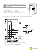
Mechanical Characteristics
Dimensions
Length: 1680mm (66.14”)
Width: 837mm (32.95”) Depth: 50mm (1.97”)
Weight 15.4 kg (33.95 pounds)
Solar Cells 50 cells (156mm x 156mm) in a 5x10 matrix connected in series
Output Cables
RHW
-2 A
WG# 12 (4mm
2
), cable with polarized weatherpr
oof DC rated Multicontact
connectors; asymmetrical lengths - 1250mm (-) and 800mm (+)
Diodes
IntegraBus™ technology includes Schottky by-pass diodes
integrated into the printed cir
cuit board bus
Construction
Front: High-transmission 3mm (1/8th in) tempered glass; Back: Tedlar; Encapsulant: EVA
Frame
S Anodized aluminium alloy type 6063T6 Universal frame; Color: silver
B Anodized aluminium alloy type 6063T6 Universal frame; Color: br
onze
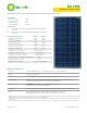
Electrical Characteristics
2
SX 3195 SX3190
Maximum power (P
m
ax
)
3
195W
190W
Voltage at P
max
(V
mp
) 24.4 24.3V
Current at P
max
(I
mp
) 7.96A 7.82A
Warranted minimum P
max
177.5W 172.9W
Short-circuit current (I
sc
) 8.6A 8.5A
Open-circuit voltage (V
oc
) 30.7V 30.6V
Temperature coefficient of I
sc
(0.065±0.015)%/ °C
Temperature coefficient of V
oc
-(111±10)mV/°C
Temperature coefficient of power -(0.5±0.05)%/°C
NOCT (Air 20°C; Sun 0.8kW/m
2
; wind 1m/s) 47
±2°C
Maximum series fuse rating 15A
Maximum system voltage 600V (U.S. NEC rating)
Performance
Rated power (P
max
) 195W
Power tolerance ±9%
Nominal voltage 16V
Limited Warranty
1
25 years
Configuration
S Silver frame with output cables and polarized Multicontact (MC)
connectors
B Bronze frame with output cables and polarized Multicontact (MC)
connectors
1.
Module warranty: 25-year limited warranty of 80% power output; 12-year limited warranty of 90% power output; 5-year limited warranty of materials
and workmanship. See your local r
epresentative for full terms of these warranties.
2.
This data represents the performance of typical SX 3195 products, and is based on measurements made in accordance with ASTM E1036 corrected
to SRC (STC.)
3. During the stabilization pr
ocess that occurs during the first few months of deployment, module power may decrease by up to 1% from typical P
max
.