Leuze electronic Barcode Positioning System BPS 37 Technical Description
© All rights reserved, especially the right of reproduction, distribution and translation. Copying or reproductions in any form require the written consent of the manufacturer. Changes reflecting technical improvements may be made.
Leuze electronic Table of contents 1 General Information ........................................................................................................... 4 1.1 Explanation of Symbols ....................................................................................................... 4 1.2 Declaration of Conformity .................................................................................................... 4 2 Safety Notices .....................................................
Leuze electronic Table of contents 8 Operation .......................................................................................................................... 29 8.1 Display Elements ............................................................................................................... 29 9 Communicating with the Device..................................................................................... 30 9.1 Installing the "BPSConfig" software ...................................
Leuze electronic Figure 2.1: Figure 3.1: Figure 3.2: Figure 3.3: Table 4.1: Figure 4.1: Figure 4.2: Table 5.1: Figure 5.1: Figure 5.2: Figure 6.1: Figure 6.2: Figure 6.3: Figure 6.4: Table 6.1: Figure 6.5: Figure 6.6: Figure 6.7: Table 6.2: Figure 7.1: Figure 9.1: Figure 9.2: Figures and tables Example for the attachment of the sticky label with warning notices ........................... 7 BPS 37 device construction .........................................................................................
Leuze electronic General Information 1 General Information 1.1 Explanation of Symbols The symbols used in this operating manual are explained below. Attention! Pay attention to passages marked with this symbol. Failure to heed this information can lead to injuries to personnel or damage to the equipment. Attention Laser! This symbol warns of possible danger through hazardous laser radiation. Notice! This symbol indicates text passages containing important information. 1.
Leuze electronic 2 Safety Notices 2.1 Safety Standards Safety Notices The barcode positioning system BPS 37 and the optional connection units MA 4.7/MA 4D.7 have been developed, produced and tested subject to the applicable safety standards. They correspond to the state of the art. 2.2 Intended Use Attention! The protection of personnel and the device cannot be guaranteed if the device is operated in a manner not corresponding to its intended use.
Leuze electronic Safety Notices 2.3 Working Safely Attention Laser Radiation! The barcode positioning system BPS 37 operates with a red light laser of class 2 acc. to EN 60825-1 (2001/11). It also complies with the U.S. 21 CFR 1040 regulations for a class II product.
Leuze electronic Safety Notices Attention! Access to or changes on the device, except where expressly described in this operating manual, is not authorised. Safety regulations Observe the locally applicable legal regulations and the rules of the employer’s liability insurance association. Qualified personnel Mounting, commissioning and maintenance of the device must only be carried out by qualified personnel. Electrical work must be carried out by a certified electrician.
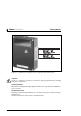
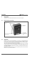
Leuze electronic Description 3 Description Information on technical data and characteristics can be found in chapter 4. 3.1 BPS 37 device construction Dovetail fastening grooves Laser-beam beam hole 15-pin sub-D connector on the underside of the unit 4 fastening threads M3 on the rear of the device Figure 3.1: BPS 37 device construction 3.2 Application Anywhere systems are moved automatically, it is necessary to correctly determine their positions.
Leuze electronic 3.3 Description Function The BPS uses visible red laser light to determine its position relative to the barcode band. This essentially takes place in three steps: 1. 2. 3.
Leuze electronic Description Without connection unit MA 4.7/MA4D.7 Voltage supply 10 … 30 V DC SI SO SSI 15 pin sub-D connector, socket version Figure 3.2: Connection BPS "Stand alone" With connection unit MA 4.7/MA4D.7 BPS 37 MA 4.7/MA 4D.7 SO SI Power SSI SSI Connection cable KB031-3000 Figure 3.3: BPS connection with connection unit MA 4.
Leuze electronic Technical Data 4 Technical Data 4.1 General Specifications BPS 37 Measurement data Reproducible accuracy Integration time Measurement value output Refresh time Scanning depth Electrical data Interface type (standard setting) Laser diode 650nm 1000scans/sec. ±1 (2) mm 16 (8) ms 500 values/sec. 90 … 170 mm Ports LED green Operating voltage Power consumption SSI (RS422) electrically isolated bits 0 … 24: data bits with position value bit 25: error bit resolution: 1mm 800 kHz max.
Leuze electronic Technical Data Barcode band Max. length (measurement length) Ambient temperature Mech. properties Table 4.1: 10000m -40°C … +120°C scratch and wipe resistant UV resistant moisture resistant partly chemical resistant General Specifications Notice! Two models of the BPS 37 are available: 4.2 BPS 37 S M 100 BPS 37 S M 100 H without optics heating with optics heating LED indicators An internal LED indicates in the reading window whether or not the supply voltage is present. 4.
Leuze electronic Technical Data Scanning curve BPS 37 BPS 37 80 60 Reading field width [mm] 40 20 Working range 0 -20 -40 -60 -80 0 25 50 75 100 125 150 175 200 225 250 Reading distance in mm TNT 35/7-24V Figure 4.
Leuze electronic Accessories / Order Designation 5 Accessories / Order Designation 5.1 Accessories Notice! Products from Leuze electronic GmbH & Co KG can be ordered from any of the sales and service offices listed on the back page of this operating manual. Designation Part No. Short Description MA 4.7 500 37324 Connection unit for BPS 37 with parameter memory MA 4D.
Leuze electronic TNT 35/7-24V Accessories / Order Designation Figure 5.1: Connection unit MA 4.7/MA 4D.
Leuze electronic Accessories / Order Designation 5.1.2 Fastening Accessories The mounting unit BT 56 is available for mounting the BPS 37. It is designed for rod installation. Mounting device BT 56 Clamping jaws for mounting on the BPS Clamp profile for mounting to round or oval pipes Ø 16 … 20mm Figure 5.2: Mounting device BT 56 5.1.3 Connection cable A special connection cable is available for the connection between BPS and connection units.
Leuze electronic 6 Installation 6.1 Storage, Transportation Installation Attention! When transporting, package the device so that it is protected against collision and humidity. Optimal protection is achieved when using the original packaging. Heed the required environmental conditions specified in the technical data. Unpacking © Check the packaging for any damage. If damage is found, notify the post office or shipping agent as well as the supplier.
Leuze electronic Installation Mounting the BPS 37 There are two basic types of mounting arrangements for the BPS 37: • using the dovetail groove and the corresponding mounting accessories (see figure 6.1) • using the fastening threads on the back- and underside of the devices (chapter 4.3) Mounting example BPS 37 Mounting device BT 56 Figure 6.1: Mounting example BPS 37 Mounting MA You can mount all connection units individually through the holes located on the mounting plate (see figure 5.1).
Leuze electronic 6.2.1 Installation Device Arrangement Selecting a mounting location In order to select the right mounting location, several factors must be considered: • The scanning range determined from the scanning curve must be adhered to at all locations at which a position determination is to be made • The BPS should be mounted inclined 10° from vertical towards the barcode band to ensure that the read results are reliably obtained even if the barcode band is soiled.
Leuze electronic Installation Minimum separation (see scanning curve) Figure 6.2: Beam outlet on the BPS 37 Mounting location © When selecting a mounting location, pay attention to • maintaining the required environmental conditions (humidity, temperature), • possible soiling of the reading window due to liquids, abrasion by boxes, or packaging material residues. • lowest possible chance of damage to the scanner by mechanical collision or jammed parts.
Leuze electronic Installation Application example 12 0 28 12 0002 812 0002 812 0002 8 Figure 6.
Leuze electronic Installation 6.3 Connection Attention! Never open the device yourself, as this may compromise protection class IP 65. Before connecting the device, be sure that the supply voltage agrees with the value printed on the nameplate. Connection of the device and maintenance work while under voltage must only be carried out by a qualified electrician.
Leuze electronic Installation Wiring description 6.3.2 Pin 1 GND Ground reference RS 232 Pin 2 SWIN1 Switching input 1 (+12 … 30VDC) Pin 3 SSI data+ SSI data line Pin 4 SSI data- SSI data line Pin 5 Reserve Pin 6 SSI clock+ SSI clock line Pin 7 /Serv Bridge to pin 15: service operation via RS232 interface Pin 8 VIN Supply voltage +10 … 30VDC Pin 9 SSI clock- SSI clock line Pin 10 SWOUT1 Switching output 1 (max.
Leuze electronic Installation Connection BPS direct BPS 37 SM 100 Control/drive SSI interface Pin SSI DATA + 3 SSI DATA - 4 SSI Clock + 6 SSI Clock - 9 Connection 1 SSI DATA + SSI DATA - Connection 2 SSI Clock + SSI Clock - Figure 6.6: Connection BPS direct Notice! Ensure adequate shielding. Connections 1 and 2 must be twisted pairs and the total connection line must be shielded and grounded at one end.
Leuze electronic 6.3.3 Installation Connection of switching input and output The BPS 37 is provided with a switching input and a switching output. The connection of the switching input and output is made according to figure 6.7: 2 SWIN1 12 … 30 V DC max. 100 mA 10 8 SWOUT1 VIN 10 … 30 V DC 15 GND Figure 6.
Leuze electronic Installation 6.3.4 Wire Lengths and Shielding The following maximum lengths for wires and the type of shielding to be used must be observed: Connecting Max. wire length Shielding BPS 37 - Service RS 232 10m absolutely required, shield meshing BPS 37/MA 4.7 Host SSI 1200m absolutely required, flexible leads as twisted pairs and shielded Switching input 10m not necessary Switching output 10m not necessary Table 6.2: 6.
Leuze electronic Commissioning 7 Commissioning 7.1 Measures to be performed prior to the initial commissioning © Before commissioning, familiarise yourself with the operation and configuration of the device(s)! © Before switching on, recheck all connections and ensure that they have been properly made. 7.2 Function Test "Power On" test After connecting the operating voltage, the BPS 37 performs an automatic "Power On" function test.
Leuze electronic Commissioning 7.3.1 Parameter sets In the BPS 37 three different parameter sets are administered: • parameter set with the default settings in the ROM • current parameter set in the EEPROM • working copy of the current parameter set in the RAM Before a parameter set is loaded into the memory of the BPS 37 processor, the validity of the parameter set is verified using checksums.
Leuze electronic Operation Service interface active The service interface is activated via a bridge between the pins 7 and 15 on the 15-pin subD connector. If the BPS 37 is operated with a connection unit, the service interface is activated through a switch in the connection unit. Connection You can connect a PC or terminal to the BPS 37 via the serial interface and configure the BPS 37 through this connection.
Leuze electronic Communicating with the Device 9 Communicating with the Device Device parameters can be set via commands or using the easy-to-use "BPSConfig 3.0" control software. 9.1 Installing the "BPSConfig" software © Place the installation CD in your CD drive. © Call up the installation file (e.g. Set-up.exe) The following window appears: Installation window Figure 9.
Leuze electronic Communicating with the Device Installation directory Figure 9.2: Installation directory © Confirm your entry with Continue, then follow the installation routine. TNT 35/7-24V For further information, please see the online help for the "BPSConfig" software.
Leuze electronic Communicating with the Device 9.2 Overview of Commands and Parameters Online commands can be used to send commands directly to the device for control and configuration. For this, the BPS 37 has to be connected to a host or service computer via the serial interface. The commands can be sent either via the host or the service interface. 9.2.
Leuze electronic 9.2.2 Communicating with the Device General parameter structure Using the BPSConfig program, parameters can be changed via the service interface. These parameters are divided into individual folders. The following folders are available: Measurement Value Control Measurement Value Preparation The various setting options are contained in the folder Measurement Value Control. These are used for activating or deactivating the measurement process.
Leuze electronic Maintenance 10 Maintenance 10.1 General Maintenance Information Usually, the barcode positioning system BPS 37 does not require any maintenance by the operator. Cleaning Should it become soiled, clean the glass window of the BPS 37 with a soft cloth. Notice! Do not use aggressive cleaning agents such as thinner or acetone for cleaning the device. 10.2 Repairs, Servicing Repairs to the device must only be carried out by the manufacturer.
Leuze electronic Leuze electronic GmbH + Co KG Postfach 11 11, D-73277 Owen/Teck Tel. (07021) 5730, Fax (07021) 573199 E-mail: info@leuze.de http://www.leuze.de Sales and Service Nortécnica S. R. L. Tel. Int. + 54 (0) 11/4757-31 29 Fax Int. + 54 (0) 11/4757 -1088 E-mail: info@nortecnica.com.ar AUS + NZ Balluff-Leuze Pty. Ltd. Tel. Int. + 61 (0) 3/9764 23 66 Fax Int. + 61 (0) 3/9753 32 62 E-mail: balluff_leuze@balluff.com.au B Leuze electronic nv /sa Tel. Int. + 32 (0) 2/2531600 Fax Int.