
User's Manual

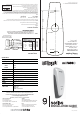


WALL VIEW
(not to scale)
Introduction
Thank you for purchasing a miPASS 9 Series Mifare Contactless Smart Card Reader. Available in 4 different
models catering for all security requirements large or small, whether your projects are price or functionality
driven. The 9 Series reader models are:
DF900 - DESFire
BT900- Mifare (standard)
miP9 - BQT SPEK
CSN9 - Card Serial Number
The 9 Series reader is used in security applications and interfaces into Wiegand applications.
The 9 Series reader is preset with specific 'Keys'. Valid smart cards are issued with the same 'Keys'. This
ensures that the system cannot be compromised. (No 'Keys" used for CSN9 model)
The reader incorporates a LED and Buzzer to provide feedback to a person wishing to enter. The control of
these is shared by the reader and security controller.
The 9 Series reader is low-profile and can be installed in new installations or as an upgraded reader in existing
proximity access control systems.
Installation
Remove the cover by holding the unit as
shown and pulling the cover from the top as illustrated
If necessary, drill holes for the mounting screws in the wall or mounting box on which the reader unit will be
placed. (Use the Drilling Template provided).
1. Place the controller and power supply cable through the Grommit hole.
2. Drill the holes as indicated by the arrows.
Note: Make sure that you don't drill through the cable.
Check your circuit diagram for the colour coding of the circuit wiring. The reader can be damaged beyond
repair if the wiring is connected incorrectly.
If the reader has the same power supply as the door latch relay, make sure that the relay is
protected by a fast Schottky diode. If the relay is not protected reader operation will be affected.
NOTE: Power to the unit is provided from the Listed control unit or from a separately supplied UL Listed
12 Vdc power-limited, access control power source.
Wiring methods shall be in accordance with the National Electrical Code, ANSI/NFPA 70.
1. Connect the 0V wire to the Power 0V line.
NOTE: The 0V line of all power supplies MUST be connected to a common 0V reference point.
2. Connect the Wiegand signal cables.
3. Connect the Buzzer and the LED cables.
4. Attach the 12Vdc wire last.
5. Place the reader on the wall (Make sure the wires are not crushed)
6. Insert and hand tighten the screws.
7. Check that the reader is level before tightening the screws.
NOTE: Excessive tightening of screws may deform the casing, resulting in a damaged unit.
This will void the warranty.
8. Replace the cover.
9. Power up the reader.
NOTE: The unit needs up to 15 seconds to set up before it can respond to a valid smart card.
External Use
Mount the reader on a suitable external single gang surface mount box.
USA ONLY - BQT mounting plate adaptor is available for mounting to a US single gang box.
Make sure that the wire bundle to the 9 Series reader has an IP rating of at least IP67.
Use warming pads if the temperature of the reader is expected to fall below -10ºC (14ºF).
Handling
Handle the 9 Series reader with care. Do not damage/drop unit before installation.
The reader unit will not be waterproof if the casing is damaged. Replace the reader if the casing is
damaged.
Maintenance
Once installed the 9 Series reader requires no maintenance.
Troubleshooting
If the reader doesn't respond when a valid smart card is presented, check the following.
If the problem still persists then please contact your distributor for technical support and to obtain an RMA if
required.
Warranty
The 9 Series reader comes with a 5 year warranty from the date of dispatch from BQT Solutions. The
warranty is void if the instructions contained within this manual have not been adhered to.
NOTE: If reader beeps when a valid smart card is presented
then the reader is functioning.
Possible Cause
No power to the reader
Voltage to the reader is below 10V
Invalid card or card is faulty
Wiring to the controller may be faulty.
Check
Check the power supply to the reader.
Check the power supply to the reader
Check reader with another valid smart card
Check the wiring to the controller
Symptom
LED is not lit
LED is Orange or Buzzer sounds low
Reader doesn't respond
Reader beeps but lock doesn't open
45mm
62mm
➣
➣
➣➣
20mm Ø
4mm Ø
4mm Ø
C
M
Y
CM
MY
CY
CMY
K
9 series_v2.8.ai 15/08/2006 11:08:35 AM9 series_v2.8.ai 15/08/2006 11:08:35 AM