Internet Version for Reference Only DIRECT VENT GAS WATER HEATER A Spanish language version of these instructions is available by Acontacting Spanish language version of on these the company listed the instructions rating plate.is available by contacting company listed on thede rating plate. La versión espãnola estas instrucciones se puede obtener al escribirle La de estas instrucciones se de puede obtener al escribirle a en la placa especificaciones.
Internet Version for Reference Only CONGRATULATIONS! You have just purchased one of the finest water heaters on the market today! This installation, operation and instruction manual will explain in detail the installation and maintenance of your new Direct Vent Gas Water Heater. The Manufacturer strongly recommends that you contact a plumbing professional for the installation of this water heater.
Internet Version for Reference Only TABLE OF CONTENTS Page GENERAL INFORMATION ..................................................... 4 INSTALLATION Locating The Water Heater ........................................................ 5 Minimum Clearances.................................................................. 8 Optional Direct Vent-Air Intake Terminal Guard ...................... 8 Venting.........................................................................................
Internet Version for Reference Only GENERAL INFORMATION This gas-fired water heater’s design is certified by CSA International under the American National Standard Z21.10.1 - (as indicated on the rating plate) and CSA 4.1-M - (as indicated on the rating plate). This water heater must be installed in accordance with local codes or, in the absence of local codes, the National Fuel Gas Code, ANSI Z223.1-Latest Edition) and/or in Canada CAN/CGA B149 Installation Codes (Latest Editions).
Internet Version for Reference Only General Information continued- A sacrificial anode is used to extend tank life. The removal of this anode, for any reason, will nullify the warranty. In areas where water is unusually active, an odor may occur at the hot water faucet due to a reaction between the sacrificial anode and the impurities in the water. If this should happen, an alternative anode may be purchased from the supplier that installed this water heater.
Internet Version for Reference Only Installation (Locating The Water Heater) continued- Note: For California installation this water heater must be braced, anchored, or strapped to avoid falling or moving during an earthquake. See instructions for correct installation procedures. Instructions may be obtained from California Office of the State Architect, 400 P Street, Sacramento, CA 95814. Water heater corrosion and component failure can be caused by the heating and breakdown of airborne chemical vapors.
Internet Version for Reference Only Installation (Locating The Water Heater) continued- WARNING DO NOT ATTEMPT TO LIGHT ANY GAS APPLIANCE IF YOU ARE NOT CERTAIN OF THE FOLLOWING: • • • • • • Liquefied petroleum gases/propane gas and natural gas have an odorant added by the gas supplier that aids in the detection of the gas. Most people recognize this odor as a “sulfur” or “rotten egg” smell.
Internet Version for Reference Only Installation continued- MINIMUM CLEARANCES WARNING Failure to adhere to these installation and operating instructions may create a hazard to life and property and will nullify the warranty. This installation shall allow access to the front of the water heater and adequate clearance shall be provided for servicing and operating this water heater. The water heater may be installed on either a combustible or non-combustible floor.
Internet Version for Reference Only Installation (Minimum Clearances) continued- Figure 1A.
Internet Version for Reference Only Installation (Minimum Clearances) continued- Figure 1B. Figure 2.
Internet Version for Reference Only Installation (Minimum Clearances) continued- Figure 3. Figure 4.
Internet Version for Reference Only Installation continued- VENTING This is a Direct Vent Gas Water Heater where all air for combustion is obtained from the outside atmosphere and all flue gases are discharged to the outside atmosphere. WARNING The vent-air intake system must be properly installed. Failure to properly install the vent-air intake system properly could result in property damage, personal injury or death. DO NOT install any damaged vent-air intake system components.
Internet Version for Reference Only Installation (Venting) continuedF= G= Clearance to inside corner Clearance to each side of center line extended above meter/regulator assembly I= Clearance to service regulator vent outlet or oil tank vent Clearance to non-mechanical air supply inlet to building or the combustion air inlet to any other appliance K= L= M= 1 US Installations2 *b *b 3 feet (91 cm) within a height 15 feet (4.
Internet Version for Reference Only Installation (Venting) continued- The co-axial vent-air intake tubes of this water heater can be installed in any 360° configuration as long as the proper clearances for installation, plumbing, operation and servicing are maintained. (See Figure 6). Figure 6. Note: Maintain proper clearances for installation, plumbing, operation and service.
Installation (Horizontal and Vertical Vent-Air Intake Lengths) continued- The following components are found in the standard vent and air intake kit, P/N 239-42979-00 (kit H). This kit, as well as all optional vent and air intake kits must be ordered separately from the manufacturer shown on the rating plate. 4” Vent Tube* 6” Air Intake Tube Vent Terminal Inner Wall Term. Mounting Flange Outer Wall Term.
Internet Version for Reference Only Installation (Horizontal and Vertical Vent-Air Intake Lengths) continued- Figure 7.
Internet Version for Reference Only Installation continued- VENT-AIR INTAKE SYSTEM INSTALLATION WARNING The vent-air intake system must be properly installed. Failure to properly install the vent-air intake system could result in property damage, personal injury or death. Do not install any damaged vent-air intake system components. Contact the manufacturer of the water heater for replacement parts.
Internet Version for Reference Only Installation (Vent-Air Intake System Installation) continued- 1. Measure the vertical height “Y” required in your installation. (See Figure 7). Reference the appropriate Table A to determine number of vent-air intake kits required in your installation. 2. Measure the horizontal length “X” required in your installation (See Figure 7). Reference Table A to determine number of vent-air intake kits required in your installation. 3. Cut a 6-1/2 inch (16.
Internet Version for Reference Only Installation (Vent-Air Intake System Installation) continued- IMPORTANT The following instructions detail the installation of the standard horizontal vent-air intake kit supplied with the water heater. 5. Insert the straight end of the four (4) inch (10.2 cm) diameter elbow into the flue reducer until firmly seated and oriented in the correct direction. With a 1/8 inch (3.
Internet Version for Reference Only Installation (Vent-Air Intake System Installation) continued- Figure 10. 7. Extend the four (4) inch (10.2 cm) diameter telescopic tube to its maximum length and slide the backing plate over it. Place the large end of the four (4) inch (10.2 cm) diameter telescopic tube through the hole in the outside wall. Insert the smaller end of the four (4) inch diameter (10.2 cm) telescopic tube into the flared end of the four (4) inch (10.2 cm) diameter elbow, one (1) inch (2.
Internet Version for Reference Only Installation (Vent-Air Intake System Installation) continued- Figure 11. 8. Extend the six (6) inch (15.2 cm) diameter telescopic tube to its maximum length. Place the large end of the six (6) inch (15.2 cm) diameter telescopic tube over the collar on the outer wall mounting plate. Drill three (3) 1/8 inch (3.2 mm) diameter holes, 120o apart, through the six (6) inch (15.2 cm) diameter telescopic tube into the collar on the outer wall mounting plate.
Internet Version for Reference Only Installation (Vent-Air Intake System Installation) continued- 9. From outside the building, slide the six (6) inch (15.2 cm) diameter telescopic tube through the opening in the wall until the outer wall mounting plate is flush with the wall (See Figure 13). Figure 13. 10. Using the supplied special RTV silicone sealant, apply a bead one (1) inch (2.5 cm) from the end of the four (4) inch (10.2 cm) diameter tube that is part of the vent-air intake terminal.
Internet Version for Reference Only Installation (Vent-Air Intake System Installation) continued- Figure 14. 11. From inside the building, slide the backing plate over the six (6) inch (15.2 cm) diameter telescopic tube until it is flush with the wall. Adjust the length of the six (6) inch (15.2 cm) diameter telescopic tube and insert the end into the flared end of the six (6) inch (15.2 cm) diameter elbow one (1) inch (2.5 cm) (or until seated). Drill three (3) 1/8 inch (3.
Internet Version for Reference Only Installation (Vent-Air Intake System Installation) continued- 12. Mark the mounting screw hole locations for the backing plate. Rotate the backing plate in order to gain access to the markings. With a 3/16 (4.75 mm) inch diameter drill bit (not supplied), drill holes for the supplied wall anchors. Install the wall anchors and secure the backing plate to the wall with four (4) #10 x 1 inch screws (supplied) (See Figure 16).
Internet Version for Reference Only Installation continued- WATER CONNECTIONS Note: BEFORE PROCEEDING WITH THE INSTALLATION, CLOSE THE MAIN WATER SUPPLY VALVE. After shutting off the main water supply, open a faucet to relieve the water line pressure to prevent any water from leaking out of the pipes while making the water connections to the water heater. After the pressure has been relieved, close the faucet. The COLD water inlet and HOT water outlet are identified on the top of the water heater.
Internet Version for Reference Only Installation (Water Connections) continued- WARNING For protection against excessive temperatures and pressure, install temperature and pressure protective equipment required by local codes, but not less than a combination temperature and pressure relief valve certified by a nationally recognized testing laboratory that maintains periodic inspection of production of listed equipment or materials as meeting the requirements of the Standard for Relief Valves and Automatic
Internet Version for Reference Only Installation (Water Connections) continued- WARNING FAILURE TO INSTALL AND MAINTAIN A NEW, LISTED 3/4” X 3/4” TEMPERATURE AND PRESSURE RELIEF VALVE WILL RELEASE THE MANUFACTURER FROM ANY CLAIM, WHICH MIGHT RESULT FROM EXCESSIVE TEMPERATURES AND PRESSURES. If this water heater is installed in a closed water supply system, such as the one having a back-flow preventer in the cold water supply, provisions shall be made to control thermal expansion.
Internet Version for Reference Only Installation (Water Connections) continued- 28
Internet Version for Reference Only Gas Connections The gas supply lines must meet all requirements of the National Fuel Gas Code (ANSI Z223.1-Latest Edition), or in Canada CAN/CGA B149.1 Natural Gas Installation Code (Latest Edition) or CAN/CGA B149.2 Propane Installation Code (Latest Edition). The minimum permissible gas supply pressure for the purpose of input adjustment is one (1.0) inch (0.25 kPa) water column above the operating manifold pressure.
Internet Version for Reference Only GENERAL OPERATION WARNING Water heaters are heat-producing appliances. To avoid damage or injury, do not store materials against the water heater or vent-air intake system. Use proper care to avoid unnecessary contact (especially by children) with the water heater and vent-air intake system.
Internet Version for Reference Only Lighting and Shutdown Instructions FOR YOUR SAFETY READ BEFORE LIGHTING WARNING: If you do not follow these instructions exactly, a fire or explosion may result causing property damage, personal injury or loss of life. A. This appliance has a pilot which is lit by a piezo-electric spark gas ignition system. Do not open the inner door and attempt to light the pilot by hand. B. BEFORE LIGHTING smell all around the appliance area for gas.
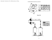
Internet Version for Reference Only THERMOSTAT ADJUSTMENT 160°F Control 180°F Control Figure 17 The thermostat dial is set to its lowest temperature setting when shipped from the factory. Remember that lower temperature settings are more energy efficient. Adjust the temperature by turning the thermostat dial. It is suggested that the starting point setting not be greater than the ” “ or “ “mark on the thermostat dial (approximately 120°F [48.9°C]) as indicated below.
Internet Version for Reference Only DANGER Hotter water increases the risk of scald injury. Scalding may occur within five (5) seconds at a temperature setting of 140° F (60° C). To protect against hot water injury, install an ASSE approved mixing valve in the water system. This valve will reduce point of discharge temperature by mixing cold and hot water in branch water lines. A licensed plumbing professional or local plumbing authority should be consulted.
Internet Version for Reference Only MAINTENANCE WARNING Water heaters are heat-producing appliances. To avoid damage or injury, do not store materials against the water heater or vent-air intake system. Use proper care to avoid unnecessary contact (especially by children) with the water heater and vent-air intake system.
Internet Version for Reference Only Maintenance (continued)- 6. Annually remove the inner door and main burner assembly to clean orifices and related parts of any dirt or other foreign material. Inspect the burner ports for obstructions or debris and clean with a wire brush as needed. Wire brush and/or vacuum clean the combustion chamber as needed to remove scale deposits and debris. Inspect the inner door gasket for wear and tear and replace if necessary.
Internet Version for Reference Only Maintenance (continued)- CAUTION FOR YOUR SAFETY. DO NOT ATTEMPT REPAIR OF COMBINATION GAS CONTROL, BURNERS OR GAS PIPING. REFER REPAIRS TO A QUALIFIED SERVICE TECHNICIAN. Contact your supplier or plumbing professional for replacement parts or contact the company at the address given on the rating plate of the water heater. Provide the part name, model and serial numbers of the water heater when ordering parts.
Internet Version for Reference Only PARTS LIST PART NAME & DESCRIPTION 1. 8. 9. 10. 11. 12. Direct Vent-Air Intake Terminal Outer Wall Mounting Plate Backing Plate Six (6) inch (15.2) Diameter Telescopic Air Intake Tube Four (4) inch (10.2) Diameter Telescopic Vent Tube Six (6) inch (15.2) Diameter Elbow Four (4) inch (10.2) Diameter Elbow Plenum Plenum Gasket Flue Reducer Jacket Top Insulation 28. 29. 30. 31A. 31B. 13. 14. Glass Lined Tank Flue Baffle Assembly 32. 33A. 15. Dip Tube & Nipple 33B.
Internet Version for Reference Only DIRECT VENT WATER HEATER 38
Internet Version for Reference Only VENT-AIR INTAKE KITS 39
Internet Version for Reference Only THE FOLLOWING INSTRUCTIONS ARE FOR INSTALLATION OF: GAS WATER HEATERS SUITABLE FOR WATER (POTABLE) HEATING AND SPACE HEATING 1. All piping components connected to this water heater for space heating applications must be suitable for use with potable water. In Massachusetts, space heating piping length must not exceed 50 feet. 2. Toxic chemicals, such as those used for boiler treatment, must not be introduced into potable water used for space heating. 3.