SETBACK CONTROL This manual must be used in conjunction with the Installation and Operation Manual for the water heater. Ambler, PA 19002 www.bradfordwhite.com Tech. Service.......................... (800) 334-3393 Service Parts ......................... (800) 538-2020 Warranty Department ............ (800) 531-2111 - Do not store or use gasoline or other flammable vapors and liquids in the vicinity of the water heater or any other appliance.
Important Information CONGRATULATIONS! You have just purchased one of the finest water heater accessories on the market today! This Installation and Operation Manual will explain in detail how to install and operate your new Setback Control. We strongly recommend you contact a plumbing professional for the installation of this new control. We require that you carefully read this manual and the manual supplied with the water heater when questions arise.
Important Information READ CAREFULLY The following terms are used throughout this manual to bring attention to the presence of hazards at various risk levels, or to important information concerning product life. DANGER CAUTION Indicates an imminently hazardous situation, which, if not avoided, will result in death, serious injury or substantial property damage. Indicates potentially hazardous situation, which, if not avoided, may result in moderate or minor injury or property damage.
Important Information Water temperature over 125°F can cause severe burns instantly or death from scalds. Children, disabled and elderly are at highest risk of being scalded. Review this instruction manual before setting temperature at water heater. Feel water before bathing or showering. Temperature limiting valves are available. CAUTION This water heater, when set at a lower temperature setting, is not capable of producing hot water of sufficient temperature for sanitizing purposes.
Table of Contents Page Installing the Setback Control........................................................ 6 Remote Mounting the Setback Control.......................................... 9 Changing the Batteries ................................................................ 21 Overview of Control Display and Buttons .................................... 24 Display Key ................................................................................. 25 Display Features ..................................
Installing the Setback Control This section covers the installation of the Setback Control to the Setback Control Junction Box Assembly, which is mounted to the water heater. The Setback Control Junction Box Assembly was already factory installed or installed as part of the Performance Package. Unplug the Water Heater and Setback Control Step 1: Unplug the water heater and Setback Control. This is shown in Figure 1.
Installing the Setback Control Removal of Setback Control Protective Plate Step 3: Remove the Setback Control Protective Plate from the Setback Control by pulling these components in opposite directions, as shown in Figure 3. Retain the protective plate if the Setback Control will be remote mounted. Setback Control Setback Control Protective Plate Figure 3 Install Batteries Step 4: Remove the battery holder from the Setback Control, and install (2) AAA batteries.
Installing the Setback Control Installing Setback Control Step 5: Using the Setback Control Junction Box Assembly (already installed on water heater), snap the Setback Control into the backplate connected to the Setback Control Junction Box Assembly, as shown in Figure 5. Setback Control Junction Box Assembly Setback Control Figure 5 Backplate already installed Powering the Water Heater and Setback Control Step 6: Plug in the water heater and the transformer to power the Setback Control.
Remote Mounting the Setback Control In the following section, the instructions detail how to Remote Mount the Setback Control. Unplug the Water Heater and Setback Control Step 1: Unplug the water heater and Setback Control. This is shown in Figure 7. Figure 7 Remove the Setback Control from the Backplate Step 2: Remove the Setback Control from the backplate attached to the Setback Control Junction Box Assembly. Some force may be required. This is shown in Figure 8.
Remote Mounting the Setback Control Prepare the Backplate for Wiring Step 3: Loosen the (3) slotted screws on the backplate attached to the Setback Control Junction Box Assembly. This is shown in Figure 9. Slotted head screws Slotted head screwdriver Setback Control Junction Box Assembly Backplate (already installed) Figure 9 Mount the Protective Plate Step 4: Mount the Setback Control Protective Plate in a desired location.
Remote Mounting the Setback Control Measure Wire for Remote Mounting Step 5: Measure and cut (3) pieces of 18 AWG wire to a sufficient length to reach from the backplate on the Setback Control Junction Box Assembly to the Setback Control Protective Plate. This is shown in Figure 11. 18 AWG Wire Figure 11 Label the Wires for Remote Mounting Step 6: Label the (3) cut wires (A), (B), and (C) respectively. Label both ends of the wires. This is shown in Figure 12. Masking tape can be used to label the wires.
Remote Mounting the Setback Control Prepare the Wires for Installation Step 7: Strip approximately ¼” of the wire’s insulation from each end of the three wires. This is shown in Figure 13. Strip Approximately ¼” from Each End of All (3) Wires Figure 13 Install Wire (A) – Backplate Step 8: Using wire (A), insert one end into the top terminal location on the backplate (located on the Setback Control Junction Box Assembly). This is shown in Figure 14.
Remote Mounting the Setback Control Fasten Wire (A) into its Designated Location – Backplate Step 9: Tighten the slotted screw in the top terminal location on the backplate (located on the Setback Control Junction Box Assembly). This is shown in Figure 15.
Remote Mounting the Setback Control Fasten Wire (B) into its Designated Location – Backplate Step 11: Tighten the slotted screw in the middle terminal location on the backplate (located on the Setback Control Junction Box Assembly). This is shown in Figure 17. Wire (A) Wire (B) Backplate Slotted head screwdriver Figure 17 Install Wire (C) – Backplate Step 12: Using wire (C), insert one end into the bottom terminal location on the backplate (located on the Setback Control Junction Box Assembly).
Remote Mounting the Setback Control Fasten Wire (C) into its Designated Location – Backplate Step 13: Tighten the slotted screw in the bottom terminal location on the backplate (located on the Setback Control Junction Box Assembly). This is shown in Figure 19. Wire (A) Wire (B) Wire (C) Setback Control Junction Box Assembly Slotted head screwdriver Figure 19 Route Wires to Protective Plate Step 14: Route all three wires to the Setback Control Protective Plate.
Remote Mounting the Setback Control Install Wire (A) – Protective Plate Step 15: Using wire (A), insert one end into the top terminal location on the Protective Plate. This is shown in Figure 20. Wire (A) Protective Plate Figure 20 Fasten Wire (A) into its Designated Location – Protective Plate Step 16: Tighten the slotted screw in the top terminal location on the Protective Plate. This is shown in Figure 21.
Remote Mounting the Setback Control Install Wire (B) – Protective Plate Step 17: Using wire (B), insert one end into the middle terminal location on the Protective Plate. This is shown in Figure 22. Wire (A) Wire (B) Protective Plate Figure 22 Fasten Wire (B) into its Designated Location – Protective Plate Step 18: Tighten the slotted screw in the middle terminal location on the Protective Plate. This is shown in Figure 23.
Remote Mounting the Setback Control Install Wire (C) – Protective Plate Step 19: Using wire (C), insert one end into the bottom terminal location on the Protective Plate. This is shown in Figure 24. Wire (A) Wire (B) Protective Plate Wire (C) Figure 24 Fasten Wire (C) into its Designated Location – Protective Plate Step 20: Tighten the slotted screw in the bottom terminal location on the Protective Plate. This is shown in Figure 25.
Remote Mounting the Setback Control Install Setback Control Step 21: Snap the Setback Control into the Protective Plate. Align the Setback Control to the Protective Plate, and press until it is fully seated. This is shown in Figure 26. Setback Control Protective Plate Figure 26 Install Cover Plate Step 22: Snap the Setback Cover Plate onto the backplate (located on the Setback Control Junction Box Assembly). This is shown in Figure 27.
Remote Mounting the Setback Control Powering the Water Heater and Setback Control Step 23: Plug in the water heater and the transformer to power the Setback Control. This is shown in Figure 28.
Changing the Batteries This section covers the replacement of the batteries used as a back-up power source for the Setback Control. Unplug the Water Heater and Setback Control Step 1: Unplug the water heater and Setback Control. This is shown in Figure 29. Figure 29 Removal of Setback Control Junction Box Assembly Cover Step 2: Remove Setback Control Junction Box Assembly cover by unscrewing the two Philips head screws holding it to the Setback Control Junction Box Assembly base.
Changing the Batteries Removal of Battery Holder Step 3: Remove the battery holder by depressing its top edge and pulling the holder to the right, as shown in Figure 31. Battery Holder Figure 31 Replacement of Batteries Step 4: Replace the two batteries with (2) AAA batteries. The batteries should be oriented, as shown in Figure 32.
Changing the Batteries Re-installation of Setback Control Junction Box Assembly Cover Step 6: Place the cover back on the Setback Control Junction Box Assembly and reinstall the Philips head screws previously removed, as shown in Figure 34. Figure 34 Powering the Water Heater and Setback Control Step 7: Plug in the water heater and transformer to power the Setback Control. This is shown in Figure 35.
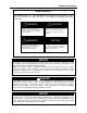
Overview of Control Display and Buttons The image, below, shows the Setback Control with all of its options shown on the screen. When the Setback Control is in use, only some of these items will be shown.
Display Key and Features Display Key: Wake: the time when the water heater setpoint should be raised to an appropriate temperature for its use. Leave: the time when the water heater setpoint should be lowered when little to no hot water is needed. Return: the time when the water heater setpoint should be raised for your return and eventual need for hot water. Sleep: the time when the water heater setpoint should be lowered when no hot water is needed for the day.
Sunday Saturday Friday Thursday Wednesday Tuesday Monday Start Time Leave Return Sleep Water Water Water Water Start Time Start Time Start Time Temperature Temperature Temperature Temperature Wake Reference Time / Water Temperature Table The table, shown below, can be filled out with your schedule for future reference.
The Start-up Procedure This section covers what steps need to be performed when the Setback Control is installed on a water heater. Screen When Power is Applied Step 1: Initially, all the segments on the screen are shown when the Setback Control is powered up. This is shown in Figure 38. Figure 38 Revision Level Screen Step 2: After a few seconds, the software revision level of the Setback Control is shown. An example is shown in Figure 39.
The Start-up Procedure Locking in the Correct Hour Step 4: When the correct hour is shown, press the RIGHT (Next) button. This is shown in Figure 41. Figure 41 Select the Correct Minute Step 5: Using the UP (increase minute) or DOWN (decrease minute) buttons, adjust the minute until the correct minute is shown. This process is shown in Figure 42. Minute digits are flashing Figure 42 Lock in the Correct Minute Step 6: When the correct minute is shown, press the RIGHT (Next) button.
The Start-up Procedure Select AM / PM Step 7: Next, the AM / PM symbol will begin to flash. Using the UP (index AM / PM) or DOWN (index AM / PM) buttons, select AM / PM. See Figure 44. "AM"/"PM" flashes Figure 44 Lock in AM / PM Step 8: Press the RIGHT (Next) button to proceed. This is shown in Figure 45. Figure 45 Select the Day Step 9: Finally, select the day. A day will be flashing initially.
The Start-up Procedure Finishing the Start-up Procedure Step 10: Press the LEFT (Done) button, as shown in Figure 47. This completes the Setback Control Start-up Procedure. You will now be taken to the HOME screen.
Setting the Setback Control Schedule – Initial Set-up Once the Setback Control Start-up procedure has been performed, the Setback schedule must be entered. This section gives step-by-step instructions on how to enter the Setback schedule. Setting the Schedule Step 1: From the Home screen, press the RIGHT (Schedule) button, as shown in Figure 48. Figure 48 Select the Day Step 2: Monday is flashing initially. Press the RIGHT (Next) button to proceed to the Wake Period for Monday. This is shown in Figure 49.
Setting the Setback Control Schedule – Initial Set-up Lock in Wake Period Start Time Step 4: Press the RIGHT (Next) button to lock in the Wake Period start time, as shown in Figure 51. Figure 51 Select AM / PM Step 5: Using the UP (index AM / PM) or DOWN (index AM / PM) buttons, select AM / PM, as shown in Figure 52. "AM"/"PM" flashes Figure 52 Lock in AM / PM Step 6: Press the RIGHT (Next) button to lock in AM / PM. This is shown in Figure 53.
Setting the Setback Control Schedule – Initial Set-up Select the Wake Period Water Temperature Step 7: Using the UP (increase water temperature) or DOWN (decrease water temperature) buttons, select the desired water temperature. This is shown in Figure 54. Temperature digits are flashing Figure 54 Lock in Wake Period Water Temperature Step 8: Press the RIGHT (Next) button to lock in the Wake period water temperature, as shown in Figure 55.
Setting the Setback Control Schedule – Initial Set-up Lock in Leave Period Start Time Step 10: Press the RIGHT (Next) button to set the Leave start time, which is shown in Figure 57. Figure 57 Select AM / PM Step 11: Next, using the UP (index AM / PM) or DOWN (index AM / PM) buttons, select AM / PM, as shown in Figure 58. "AM"/"PM" flashes Figure 58 Lock in AM / PM Step 12: Press the RIGHT (Next) button to lock in AM / PM. This is shown in Figure 59.
Setting the Setback Control Schedule – Initial Set-up Select the Leave Period Water Temperature Step 13: Using the UP (increase water temperature) or DOWN (decrease water temperature) buttons, select the desired water temperature for the Leave period. This is shown in Figure 60. Temperature digits are flashing Figure 60 Lock in Leave Period Water Temperature Step 14: Press the RIGHT (Next) button to lock in the Leave period water temperature, as shown in Figure 61.
Setting the Setback Control Schedule – Initial Set-up Lock in Return Period Start Time Step 16: Press the RIGHT (Next) button to set the Return period start time, which is shown in Figure 63. Figure 63 Select AM / PM Step 17: Next, using the UP (index AM / PM) or DOWN (index AM / PM) buttons, select AM / PM, as shown in Figure 64. "AM"/"PM" flashes Figure 64 Lock in AM / PM Step 18: Press the RIGHT (Next) button to lock in AM / PM. This is shown in Figure 65.
Setting the Setback Control Schedule – Initial Set-up Select the Return Period Water Temperature Step 19: Using the UP (increase water temperature) or DOWN (decrease water temperature) buttons, select the Return period water temperature. This is shown in Figure 66. Temperature digits are flashing Figure 66 Lock the Return Period Water Temperature Step 20: Press the RIGHT (Next) button to lock in the Return period water temperature, as shown in Figure 67.
Setting the Setback Control Schedule – Initial Set-up Lock the Sleep Period Start Time Step 22: Press the RIGHT (Next) button to set the Sleep period start time, which is shown in Figure 69. Figure 69 Select AM / PM Step 23: Next, using the UP (index AM / PM) or DOWN (index AM / PM) buttons, select AM / PM, as shown in Figure 70. "AM"/"PM" flashes Figure 70 Lock in AM / PM Step 24: Press the RIGHT (Next) button to lock in AM / PM. This is shown in Figure 71.
Setting the Setback Control Schedule – Initial Set-up Select Sleep Period Water Temperature Step 25: Using the UP (increase water temperature) or DOWN (decrease water temperature) buttons, select the desired Sleep period water temperature. This is shown in Figure 72. Temperature digits are flashing Figure 72 Lock in Sleep Period Water Temperature Step 26: Press the RIGHT (Next) button, as shown in Figure 73. Now, the Sleep time period is set for Monday. This completes the one day of the Setback schedule.
Editing the Setback Schedule If the Setback schedule needs to be modified at any point, the instructions in this section can be followed to edit the previously entered water temperatures and times. Enter Editing the Schedule Mode Step 1: From the Home screen, press the RIGHT (Schedule) button, as shown in Figure 75. Figure 75 Select the Day to Edit Step 2: Monday is flashing initially. Using the UP (increase day) or DOWN (decrease day) buttons, scroll until the day that needs to be edited is shown.
Editing the Setback Schedule Edit the Wake Period Start Time Step 4: Press the UP (increase time by 15 minutes) or DOWN (decrease time by 15 minutes) buttons until the wanted time is shown. This is shown in Figure 78. Hour & minutes digits are flashing Figure 78 Lock in the Wake Period Start Time Step 5: Press the RIGHT (Next) button to lock the Wake period start time for the day selected, as shown in Figure 79.
Editing the Setback Schedule Lock in AM / PM Step 7: Press the RIGHT (Next) button to select AM / PM. This is shown in Figure 81. Figure 81 Edit the Wake Period Water Temperature Step 8: Using the UP (increase water temperature) or DOWN (decrease water temperature) buttons, select the Wake period desired water temperature. This is shown in Figure 82.
Editing the Setback Schedule Edit the Leave Period Start Time Step 10: Press the UP (increase time by 15 minutes) or DOWN (decrease time by 15 minutes) buttons to edit the Leave period start time. The time increments in 15-minute intervals just as it did for the Wake period. This is shown in Figure 84. Hour & minutes digits flash Figure 84 Lock in the Leave Period Start Time Step 11: Press the RIGHT (Next) button to lock in the Leave period start time, which is shown in Figure 85.
Editing the Setback Schedule Lock in AM / PM Step 13: Press the RIGHT (Next) button to lock in AM / PM. This is shown in Figure 87. Figure 87 Edit the Leave Period Water Temperature Step 14: Using the UP (increase water temperature) or DOWN (decrease water temperature) buttons, set the Leave period desired water temperature. This is shown in Figure 88.
Editing the Setback Schedule Edit the Return Period Start Time Step 16: Press the UP (increase time by 15 minutes) or DOWN (decrease time by 15 minutes) buttons to edit the time that this period becomes active. The time increments in 15-minute intervals just as it did for the Wake period. This is shown in Figure 90. Hour & minutes digits are flashing Figure 90 Lock in the Return Period Start Time Step 17: Press the RIGHT (Next) button to lock in the Return period start time, which is shown in Figure 91.
Editing the Setback Schedule Lock in AM / PM Step 19: Press the RIGHT (Next) button to lock in AM / PM. This is shown in Figure 93. Figure 93 Edit the Return Period Water Temperature Step 20: Using the UP (increase water temperature) or DOWN (decrease water temperature) buttons, select the Return period desired water temperature. This is shown in Figure 94.
Editing the Setback Schedule Edit the Sleep Period Start Time Step 22: Press the UP (increase time by 15 minutes) or DOWN (decrease time by 15 minutes) buttons to edit the Sleep period start time. The time increments in 15-minute intervals just as it did for the previous periods. This is shown in Figure 96. Hour & minutes digits are flashing Figure 96 Lock in the Sleep Period Start Time Step 23: Press the RIGHT (Next) button to lock in the Sleep period time, which is shown in Figure 97.
Editing the Setback Schedule Lock in AM / PM Step 25: Press the RIGHT (Next) button to lock in AM / PM. This is shown in Figure 99. Figure 99 Edit the Sleep Period Water Temperature Step 26: Using the UP (increase water temperature) or DOWN (decrease water temperature) buttons, select the Sleep period desired water temperature. This is shown in Figure 100. Temperature digits are flashing Figure 100 Lock in the Sleep Period Water Temperature Step 27: Press the RIGHT (Next) button, as shown in Figure 101.
Editing the Setback Schedule Exiting the Edit Schedule Mode Step 28: When you are finished editing the Setback schedule, press the LEFT (Done) button to exit the Schedule editing mode, as shown in Figure 102. You will now return to the HOME screen.
Setting a Temporary Temperature Hold If an alternate water temperature is required for a short period of time, follow the instructions in this section to temporarily modify the Setback set water temperature. Setting a New Water Temperature Step 1: From the Home screen, press the UP (increase water temperature) or DOWN (decrease water temperature buttons until the new desired water temperature is shown. This is shown in Figure 103.
Setting a Permanent Temperature Hold If an alternate water temperature is required for an indefinite amount of time, follow the instructions in this section to modify the Setback water temperature for an open ended amount of time. Setting a New Water Temperature Step 1: From the Home screen, press the UP (increase water temperature) or DOWN (decrease water temperature buttons until the new desired water temperature is shown. This is shown in Figure 106.
Editing the Clock / Day This section covers how to change the Setback Control clock, as well as the day. This may become useful when time changes for daylight savings. Enter Clock / Day Editing Mode Step 1: From the Home screen, press the LEFT (Set Clock / Day) button, as shown in Figure 109. Figure 109 Select Correct Hour Step 2: Using the UP (increase hour) or DOWN (decrease hour) buttons, select the correct hour. This is shown in Figure 110.
Editing the Clock / Day Select Correct Minute Step 4: Using the UP (increase minute) or DOWN (decrease minute) buttons, adjust the minute until the correct one is shown. This process is shown in Figure 112. Minute digits are flashing Figure 112 Lock in Correct Minute Step 5: Press the RIGHT (Next) button to set the minute, which is shown in Figure 113. Figure 113 Select AM / PM Step 6: Using the UP (index AM / PM) or DOWN (index AM / PM) buttons, select AM / PM, as shown in Figure 114.
Editing the Clock / Day Lock in AM / PM Step 7: Press the RIGHT (Next) button to proceed, which is shown in Figure 115. Figure 115 Select Correct Day Step 8: Using the UP (increase day) or DOWN (decrease day) buttons, select the correct day. This process is shown in Figure 116. Day of the week flashes Figure 116 Lock in Correct Day & Complete Editing Clock / Day Mode Step 9: Press the LEFT (Done) button, which is shown in Figure 117. This completes the procedure for editing the Setback clock and day.
Sabbath Time Period Editing In order to comply with the Sabbath, follow the instructions in this section to modify the Setback schedule. Please consult your local rabbi for recommended water temperatures and appropriate times for the Sabbath. Enter Sabbath Time Period Editing Step 1: From the Home screen, press the RIGHT (Schedule) button, as shown in Figure 118. Figure 118 Select the Day to Edit Step 2: Monday is the first day that is shown flashing initially.
Sabbath Time Period Editing Edit the Wake Period Start Time Step 4: Press the UP (increase time by 15 minutes) or DOWN (decrease time by 15 minutes) buttons until the wanted time is shown. This is shown in Figure 121. Hour & minutes digits are flashing Figure 121 Lock in Wake Period Start Time Step 5: Press the RIGHT (Next) button to lock in the Wake period start time, as shown in Figure 122.
Sabbath Time Period Editing Lock in AM / PM Step 7: Press the RIGHT (Next) button to lock in AM / PM. This is shown in Figure 124. Figure 124 Edit the Wake Period Water Temperature Step 8: Using the UP (increase water temperature) or DOWN (decrease water temperature) buttons, select the Wake period desired water temperature. This is shown in Figure 125.
Sabbath Time Period Editing Edit the Leave Period Start Time Step 10: Press the UP (increase time by 15 minutes) or DOWN (decrease time by 15 minutes) buttons to edit the Leave period start time. The time increments in 15-minute intervals just as it did for the Wake period. This is shown in Figure 127. Hour & minutes digits are flashing Figure 127 Lock in Leave Period Start Time Step 11: Press the RIGHT (Next) button to lock in the Leave period start time, which is shown in Figure 128.
Sabbath Time Period Editing Lock in AM / PM Step 13: Press the RIGHT (Next) button to lock in AM / PM. This is shown in Figure 130. Figure 130 Edit Leave Period Water Temperature Step 14: Using the UP (increase water temperature) or DOWN (decrease water temperature) buttons, select the Leave period desired water temperature. This is shown in Figure 131.
Sabbath Time Period Editing Edit the Return Period Start Time Step 16: Press the UP (increase time by 15 minutes) or DOWN (decrease time by 15 minutes) buttons to edit the time the Return period start time. The time increments in 15-minute intervals just as it did for the Wake period. This is shown in Figure 133. Hour & minutes digits are flashing Figure 133 Lock in Return Period Start Time Step 17: Press the RIGHT (Next) button to lock in the Return period start time, which is shown in Figure 134.
Sabbath Time Period Editing Lock in AM / PM Step 19: Press the RIGHT (Next) button to lock in AM / PM. This is shown in Figure 136. Figure 136 Edit Return Period Water Temperature Step 20: Using the UP (increase water temperature) or DOWN (decrease water temperature) buttons, select the Return period desired water temperature. This is shown in Figure 137.
Sabbath Time Period Editing Edit Sleep Period Start Time Step 22: Press the UP (increase time by 15 minutes) or DOWN (decrease time by 15 minutes) buttons to edit the Sleep period start time. The time increments in 15-minute intervals just as it did for the previous periods. This is shown in Figure 139. Hour & minutes digits are flashing Figure 139 Lock in Sleep Period Start Time Step 23: Press the RIGHT (Next) button to lock in the Sleep period start time, which is shown in Figure 140.
Sabbath Time Period Editing Lock in AM / PM Step 25: Press the RIGHT (Next) button to lock in AM / PM. This is shown in Figure 142. Figure 142 Edit the Sleep Period Water Temperature Step 26: Using the UP (increase water temperature) or DOWN (decrease water temperature) buttons, select the Sleep period desired water temperature. This is shown in Figure 143.
Sabbath Time Period Editing Continuing with Sabbath Time Period Editing To edit the schedule for Saturday, return to Step 2 on page 55 and follow the same procedure. When you are finished changing the Setback schedule, press the LEFT (Done) button, as shown in Figure 145.
Diagnostic Codes In this section, the table details what the diagnostic codes on the Setback Control mean. The diagnostic codes that can be displayed are different and depend on the gas valve / control that is connected to the Setback Control. Diagnostic Code # Description 58 59 60 61 62 Setback Control not connected to gas valve / control or improperly wired together. Pressure switch failed to open (stuck closed). Weak pilot signal detected. Pilot signal detected out of sequence.
Notes -66-
Notes -67-
Ambler, PA For U.S. and Canada field service, contact your professional installer or local Bradford White sales representative. Sales/800-523-2931 Fax/215-641-1670 Parts Fax/215-641-2108 Technical Support/800-334-3393 Fax/269-795-1089 Warranty/800-531-2111 Fax/269-795-1089 International: Telephone/215-641-9400 Telefax/215-641-9750 Mississauga, ON Sales/866-690-0961 905-238-0100 Fax/905-238-0105 Technical Support/800-334-3393 Email: parts@bradfordwhite.com techserv@bradfordwhite.com www.bradfordwhite.