O N LY A Spanish language version of these instructions is available by contacting the company listed on the rating plate. La version espanola de estas instrucciones se puede obtener al escribirle a la fabrica cuyo nombre aparece en la placa de especificaciones.
CONGRATULATIONS! You have just purchased one of the finest water heaters on the market today! N LY This installation, operation and instruction manual will explain in detail the installation and maintenance of your new Gas Water Heater. We at Bradford White strongly recommend that you contact a plumbing professional for the installation of this water heater. This manual should be kept with the water heater.
TABLE OF CONTENTS GENERAL INFORMATION ............................................................ page 4 Locating The Water Heater .................................................... O Minimum Clearances............................................................... N LY INSTALLATION 6 9 ER EN C E Venting ...................................................................................... 10 Combustion Air Supply............................................................ 11 Water Connections...
GENERAL INFORMATION N LY This gas-fired water heater is design certified by CSA International under the applicable American National Standard, Z21.10.1 or CSA 4.1-(as indicated on the rating plate), available from CSA International, 8501 East Pleasant Valley Road, Cleveland, OH U.S.A. 44131-5575. ER EN C E O This water heater must be installed in accordance with local codes. In the absence of local codes, it must be installed in compliance with the National Fuel Gas Code (ANSI Z223.
General Information continued- IMPORTANT O N LY Before proceeding, please inspect the water heater and components for possible damage. DO NOT install any damaged components. If damage is evident then please contact the supplier where the water heater was purchased or the manufacturer listed on the rating plate for replacement parts.
INSTALLATION LOCATING THE WATER HEATER WARNING ER EN C E O N LY Water heaters are heat producing appliances. To avoid damage or injury there shall be no materials stored against the water heater or vent-air intake system and proper care shall be taken to avoid unnecessary contact (especially by children) with the water heater and vent-air intake components.
Installation (Locating The Water Heater) continued- WARNING ER EN C E O N LY Water heater corrosion and component failure can be caused by the heating and breakdown of airborne chemical vapors. Examples of some typical compounds that are potentially corrosive are: spray can propellants, cleaning solvents, refrigerator and air conditioning refrigerants, swimming pool chemicals, calcium and sodium chloride, waxes and process chemicals.
Installation (Locating The Water Heater) continued- WARNING ER EN C E O N LY DO NOT ATTEMPT TO LIGHT ANY GAS APPLIANCE IF YOU ARE NOT CERTAIN OF THE FOLLOWING: • Liquefied petroleum gases/propane gas and natural gas have an odorant added by the gas supplier that aids in detection of the gas. • Most people recognize this odor as a “sulfur” or “rotten egg” smell. • Other conditions, such as “odorant fade” can cause the odorant to diminish in intensity, or “fade”, and not be as readily detectable.
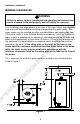
Installation (continued)- MINIMUM CLEARANCES WARNING N LY Failure to adhere to these installation and operating instructions may create a hazard to life and property and will nullify the warranty. R R EF ER EN C E O This installation shall allow access to the front of the water heater and adequate clearance shall be provided for servicing and operating this water heater. The water heater may be installed on either a combustible or non-combustible floor.
Installation (continued)- VENTING WARNING N LY The vent system must be installed properly. Failure to properly install the vent system could result in property damage, personal injury, or death. ER EN C E O Place the draft diverter over the flue opening at the top of the water heater by inserting the tips of the draft diverter legs into the four (4) holes provided in the water heater top. On some models, line up the holes in the draft diverter legs with the holes provided on top of the water heater.
Combustion Air Supply WARNING N LY Liquefied petroleum gases/propane gas are heavier than air and will remain at floor level if there is a leak. Basements, crawl spaces, closets and areas below ground level will serve as pockets for accumulation of leaking gas. Before lighting, smell all around the appliance area for gas. Be sure to smell next to the floor. ER EN C E O IF YOU SMELL GAS: • Do not try to light any appliance. • Do not touch any electric switch; do not use any telephone in your building.
Installation (continued)- ER EN C E O N LY All Air From Inside the Building: The confined space shall be provided with two permanent openings communicating directly with an additional room(s) of sufficient volume so that the combined volume of all spaces meets the criteria for an unconfined space. The total input of all gas utilization equipment installed in the combined space shall be considered in making this determination. Each opening shall have a minimum free area of 1 square inch per 1000 BTU (2.
WATER CONNECTIONS CAUTION ER EN C E O N LY Note: BEFORE PROCEEDING WITH THE INSTALLATION, CLOSE THE MAIN WATER SUPPLY VALVE. After shutting off the main water supply, open a faucet to relieve the water line pressure to prevent any water from leaking out of the pipes while making the water connections to the water heater. After the pressure has been relieved, close the faucet. The COLD water inlet and HOT water outlet are identified on the top of the water heater.
WARNING EF ER EN C E O N LY For protection against excessive temperatures and pressure, install temperature and pressure protective equipment required by local codes, but not less than a combination temperature and pressure relief valve certified by a nationally recognized testing laboratory that maintains periodic inspection of production of listed equipment or materials as meeting the requirements of the Standard for Relief Valves and Automatic Gas Shutoff Devices for Hot Water Supply Systems, ANSI Z
Installation (Water Connections) continued- WARNING ER EN C E O N LY Hydrogen gas can be produced in an operating water heater that has not had water drawn from the tank for a long period of time (generally two weeks or more). Hydrogen gas is extremely flammable. To prevent the possibility of injury under these conditions, we recommend the hot water faucet to be open for several minutes at the kitchen sink before you use any electrical appliance which is connected to the hot water system.
GAS CONNECTIONS The gas supply lines must meet all requirements of the National Fuel Gas Code ANSI Z223.1-(Latest Edition) and/or in Canada CAN/CGA B149 Installation Codes - (Latest Editions). Connect this water heater only to the type of gas (Natural or Propane gas) as shown on the rating plate. Use clean 1/2 inch black iron pipe. (Dirt and scale from the pipe can enter the combination control and cause it to malfunction). The inlet gas line must have a minimum length of 3” (7.
GENERAL OPERATION WARNING ER EN C E O N LY Water heaters are heat producing appliances. To avoid damage or injury there shall be no materials stored against the water heater or vent-air intake system, and proper care shall be taken to avoid unnecessary contact (especially by children) with the water heater and vent-air intake system.
IN TE R N ET VE R SI O N FO R R EF ER EN C E O N LY General Operation (continued)- 18
THERMOSTAT ADJUSTMENT VE R SI O N FO R R EF ER EN C E O N LY The thermostat dial is set to its lowest temperature setting when shipped from the factory. Remember that lower temperature settings are more energy efficient. Adjust the temperature by turning the thermostat dial. It is suggested that the starting point setting not be greater than the “ “ mark on the thermostat dial (approximately 120°F [49°C]) as indicated below.
General Operation (continued)- BURNER FLAME CHECKS ER EN C E O N LY Cast Iron Burner: At the time of installation and at periodic intervals (not more than 6 months), a visual check of the main burner and pilot flames should be made to determine if they are burning properly. For ideal operation, the gas and air must be properly proportioned. The proper air-gas mixture is obtained by adjusting the air shutter on the mixer face of the main burner (See Figure 3).
MAINTENANCE WARNING IMPORTANT ER EN C E O N LY Water heaters are heat producing appliances. To avoid damage or injury there shall be no materials stored against the water heater or vent-air intake system, and proper care shall be taken to avoid unnecessary contact (especially by children) with the water heater and vent-air intake system.
Maintenance (continued)- WARNING • N LY • O • Do not operate water heater with jumpered, altered, loosely tightened or absent controls and/or components. Do not operate water heater with replacement controls and/or components which are not exact duplicates or original equipment. Thoroughly inspect and replace, (as needed) burner inner door gasket and/or sight window gasket any time burner inner door is removed or disturbed. Replace water heater if involved in flammable vapors incident.
Maintenance (continued)- CAUTION N LY FOR YOUR SAFETY, DO NOT ATTEMPT REPAIR OF COMBINATION GAS CONTROL, BURNERS OR GAS PIPING. REFER REPAIRS TO A QUALIFIED SERVICE TECHNICIAN. O Contact your supplier or plumbing professional for replacement parts or contact the company at the address given on the rating plate of the water heater. ER EN C E Provide the part name, model and serial numbers of the water heater when ordering parts.
ET N R TE IN VE R Figure 5 24 N SI O R FO ER EN C E EF R O N LY
ET N R TE IN VE R N SI O R FO ER EN C E EF R O N LY PARTS LIST DRAWING 25
N LY 14. Drain Valve 2. Jacket Head Pan 15. Piezo Igniter 3. Jacket 16. Gas Valve 4. Outer Door 17. Steel Burner 5. Magnesium Anode – Hot Water Outlet 18. Orifice 6. Flue Baffle Assembly 19. Gas Feedline to Burner 7. Dip Tube – Cold Water Inlet 20. Gas Feedline to Pilot 8. Temperature and Pressure Relief Valve 21. Thermocouple Lead R R EF 1. Draft Diverter 22. Piezo Igniter Lead FO 9. Glass Lined Tank 23. Pilot Assembly 11. Jacket Base Pan 24. Cast Iron Burner N 10.
THE FOLLOWING INSTRUCTIONS ARE FOR INSTALLATION OF: GAS WATER HEATERS SUITABLE FOR WATER (POTABLE) HEATING AND SPACE HEATING 4. N LY 3. O 2. All piping components connected to this water heater for space heating applications must be suitable for use with potable water. In Massachusetts, space heating piping length must not exceed 50 feet. Toxic chemicals, such as those used for boiler treatment, must not be introduced into potable water used for space heating.
ET N R TE IN VE R N SI O R FO ER EN C E EF R O N LY NOTES 28