
Service Manual


SEQUENCE OF OPERATION
The Power Circuit Wiring Diagram illustrates the electrical connections from the incoming power supply through the
contactors to the heating elements. The power circuits are available with internal circuit fusing and without internal
circuit fusing.
As it would be impractical to show all wired configurations in this service manual, a reference wiring diagram is
illustrated below to aid in the understanding of the power circuit operating sequence. Service providers must refer to the
water heaters power circuit wiring diagram attached to the inside panel of the control cabinet for the specific connections
of the water heater being serviced.
The power circuit components and supporting information that appear on the wiring diagram include the following:
Field wiring connection via terminal block or other connection point
Fuse block with amperage ratings displayed (when provided)
Contactors with amperage ratings displayed
Electrical elements with voltage and wattage ratings displayed
Water heaters total amperage draw is displayed
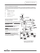
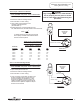
Power Circuit Description-
Line voltage is applied across terminals of fuse block
or a terminal block. Line voltage continues down and
connects to terminals L1, L2 & L3 of one or more
contactors.
A)
Contactor is open (no call for heat), so there is no
voltage across terminal T1, T2 & T3
of contactor.
B) The contactor is controlled by the control circuit
as explained on pages 10 & 11.
1
2
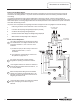
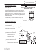
The control circuit senses a call for heat and
energizes the operating coil within the contactor.
The energized contactor coil causes the contactor to
close energizing the elements from terminals T1, T2
& T3 of the contactor.
3
When the temperature setting of the thermostat is
reached, the contacts in the thermostat open. This
interrupts current flow through the control circuit de-
energizing the contactor coil.
4
The de-energized contactor coil causes the contactor
to open, interrupting current flow through the
elements.
5
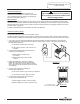
Power Circuit Sequence-
Line voltage from
service panel
Line voltage to
control circuit
Page 12
12
12