
Spec Sheet


©2019, Bradford White Corporation. All rights reserved.
For field service, contact your professional installer or local Bradford White sales representative.
Sales 800-523-2931
n
Fax 215-641-1612
Technical Support 800-334-3393
n
Email techserv
@
bradfordwhite.com
Warranty 800-531-2111
n
Email warranty
@
bradfordwhite.com
International: Telephone 1-215-641-9400
n
Email international
@
bradfordwhite.com / www.bradfordwhite.com
Ambler, PA
Printed in U.S.A.430-B-0319
Sample Specification
The water heater shall be a Bradford White model with a rated storage capacity of not less than_______gallons (_______liters), a minimum
kW input of _______kW (_______ BTU/Hr.), a minimum recovery of _______GPH (_______ LPH). The tank shall be Vitraglas
®
lined and have a
bolted hand hole cleanout. The tank shall have _______magnesium anode rods installed in separate tank head couplings. The heater shall
have 3” Non-CFC foam insulation, and come equipped with an ASME rated T&P relief valve, a cold water inlet Hydrojet
®
Sediment Reduction
System. It shall be design certified by ETL for 180ºF (82ºC) application, either with or without a separate storage tank, and comply with
state and local codes and ordinances.
General
All electric water heaters are certified at 300 PSI test pressure (2068 kPa) and 150 PSI working pressure (1034 kPa). All models are design
certified by ETL, for up to 180°F (82°C) application as an Automatic Storage Heater, and an Automatic Circulating Tank Heater. As an
Automatic Storage Heater, all models are complete, self-contained water heating systems. It needs no separate storage tank, pump, wiring
or elaborate piping network. When equipped with a mixing valve, it will supply 180°F (82°C) sanitizing and lower temperature general purpose
hot water simultaneously. These models can be used either as a single unit or in multiples connected in series or parallel (recommended).
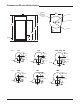
Dimensions and specifications subject to change without notice in accordance with our policy of continuous product improvement.
Optional Components
n High and Low Water Pressure Controls—The Controls interrupt the electrical current to the contactor coil when the
pressure settings are exceeded.
n Low Water Level Control—This Control will interrupt the electrical current to the contactor coil when a low water
level condition is sensed inside the water heater tank. When the low water level condition is corrected the control will
automatically sense the new situation and electrical current will again energize the contactor coil. Normal water heater
operation will be resumed.
n Alarm Horn—The Alarm Horn is an option specified when the installation desires an audible signal to immediately sound
an alert when the water heater operation is interrupted for certain faults. Referring to the control circuit wiring diagram,
the alarm will activate when any one of the following events occur:
-- The Hi-Limit control has been tripped
-- The High Water Pressure Control senses excessive pressure
-- The Low Water Pressure Control senses insufficient pressure
-- The Low Water Level Control senses an insufficient quantity of water
n Heating Element Sequencers—Heating element sequencers are available in order to stage the activation of the heating
elements thereby, reducing the inrush current to the water heater. The sequencers will control one or two contactor coils
depending upon the water heater voltage, phase, and kW.
n Electrical Door Lock—An electrical door lock is offered in order to secure the access to the water heater control
cabinet. This device will lock the control cabinet door when the 120VAC control circuit voltage is applied to it.
n Temperature and Pressure Gauge—Displays approximate temperature of the water and approximate pressure inside
the tank.
n BMS Relay.
Commercial Electric Water Heater