COMMERCIAL ELECTRIC ENERGY SAVER WATER HEATER ASME SERIES IMMERSION THERMOSTAT WITH CONTACTORS SERVICE MANUAL Troubleshooting Guide and Instructions for Service (To be performed ONLY by qualified service providers) Models Covered by This Manual: 6A, 12A, 20A, 30A, 40A, 50A, 80A, 120A Manual 238-47202-00A REV 08/18 Save this manual for future reference
ASME Series Commercial Electric Water Heaters Table of Contents Page Service Procedure Introduction ………………………………………………………………………. 2 --- Tools……………………………………………………………………………… 2 --- General Information ……………………………………………………………… 3 --- Sequence of Operation …………………………………………………………… 10 --- Troubleshooting ………………………………………………………………….. 13 --- Heating Element Testing ……………..................................................................... 15 ACE-I Line Voltage Testing………………...
GENERAL INFORMATION Model Number Breakdown 120A - 24 - 3 - 108B - BBG Pressure Gage Option. Control Circuit Option Code. Any combination of the following optional controls: - Heating Element Time Delay Sequencing. - Low Water Power Interrupt. - Panel Door Interlock - High Pressure Power Interrupt - Low Pressure Power Interrupt - Alarm Horn NOTE: Code “AA” denotes no optional controls used. Power Circuit Code.
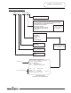
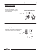
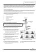
GENERAL INFORMATION General Controls Layout Control Circuit Fuse Block Control Circuit Transformer Terminal strip Pressure Gage (optional) Terminal Block Power Circuit Fuse Blocks Thermostat Control Contactors Heating Element Time Delay Sequencers (optional) Low Water Level Control (optional) High Pressure Limit Switch (optional) Low Pressure Limit Switch (optional) High Limit Immersion Bulb Thermostat Immersion Bulb High Limit (ECO) Alarm Horn Relay (optional) Alarm Horn (optional) Heating Ele
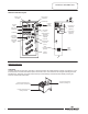
GENERAL INFORMATION Standard Controls (continued) Immersion Style Thermostat Control The thermostat will complete control circuit voltage upon a call for heat. Likewise, the control will interrupt control circuit voltage when the water temperature is sufficient to satisfy the adjustable temperature limit of control.
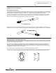
GENERAL INFORMATION Standard Controls (continued) Direct Immersion “Screw-in” Type Heating Element 2-1/8 Hex Screw-in Flange Terminal Block Screw Terminal Block Zinc Plated Copper or Incoloy Sheath Element Rating Ink Stamped on face of Terminal Block. Optional Controls Certain control components are available as “Optional“. When these optional components are installed with the water heater, the control circuit wiring diagram accordingly will include these components.
GENERAL INFORMATION Optional Controls (continued) Low Water Level Control- This control will interrupt the electrical current to the contactor coil when a low water level condition is sensed inside the water heater tank. When the low water level condition is corrected the control will automatically sense the new situation and electrical current will again energize the contactor coil. Normal water heater operation will be resumed.
GENERAL INFORMATION Optional Controls (continued) Electrical Door lock- An electrical door lock is offered in order to secure the access to the water heater control cabinet. This device will lock the control cabinet door when the 120VAC control circuit voltage is applied to it. Note: Once the door is opened, the water heater can be re-energized, if necessary, for service diagnosis.
GENERAL INFORMATION Commonly Used Formulas (balanced 3 phase) (Single phase) Watts Amps = Amps = Volts Common Service Wire Configurations Watts Ohms = Watts = Amps x Volts Volts x 1.
SEQUENCE OF OPERATION This water heater has two distinct electrical systems. One system, referred to as the “Control Circuit”, controls the water heater operation, while the other system referred to as the “Power Circuit”, connects the electrical power to the heating elements, The electrical contactors interconnect these two systems. In order to clearly illustrate the electrical circuits, two wiring diagrams are provided.
SEQUENCE OF OPERATION Control Circuit Sequence (Continued)- Certain other control components are available as “Optional“. These controls are specified when the installation has unique requirements that must be safeguarded. When these optional components are installed the control circuit wiring diagram accordingly will include these components.
SEQUENCE OF OPERATION Power Circuit Description- The Power Circuit Wiring Diagram illustrates the electrical connections from the incoming power supply through the contactors to the heating elements. The power circuits are available with internal circuit fusing and without internal circuit fusing. As it would be impractical to show all wired configurations in this service manual, a reference wiring diagram is illustrated below to aid in the understanding of the power circuit operating sequence.
TROUBLESHOOTING Most common cause for improper electric water heater operation can be linked to heating element failure. When troubleshooting an electric water heater with the incidence of “No Hot Water” or “Insufficient Amount of Hot Water” It is always a good idea to check the heating elements first following the procedure on page 15. Common Heating Element Failures Are: 1. Dry Firing. Elements may be partially submerged in water or most likely, completely exposed with no water in the tank at all.
TROUBLESHOOTING Quick Step Plan to Hot Water WARNING High voltage exposure. Use caution when making voltage checks to avoid hazard to life or property. 1. STOP, DANGER! Turn power “OFF” to water heater. 2. Check all wire connections to insure they are snug and corrosion free. 3. Reset high limit (ECO) (page 18). 4. Check for inoperative heating element (page 15). 5. Check line voltage (pg 16), and internal fuses (page 17). 6. Refer to table below if items 1 through 5 above do not correct problem.
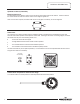
SERVICE PROCEDURE ACE-I Heating Element Testing Test for Open or Burned Out Element. 1. STOP, DANGER! Turn power “OFF” to water heater. 2. Open control panel access door. 3. Disconnect wires from heating element. DANGER High voltage exposure. To avoid hazard to Life or property, be sure power is turned OFF to water heater while performing this procedure. 4. Set multi-meter to “ohms” setting. 5. Touch probes of multi-meter to screw terminals of heating element (see illustration 1). 6.
SERVICE PROCEDURE ACE-II Line Voltage Testing DANGER High voltage exposure. To avoid hazard to life or property use extreme caution when making voltage checks . Line Voltage Testing Line voltage (single phase or three phase) will connect to a terminal block or directly to a fuse block located inside control panel. Determine heaters voltage and phase by referring to the rating plate located on the front of the heater.
SERVICE PROCEDURE ACE-III Fuse Testing Fuse Testing DANGER High voltage exposure. To avoid hazard to Life or property, be sure power is turned OFF to water heater while performing this procedure. 1. STOP, DANGER! Turn power “OFF” to water heater. 2. Open control panel door to allow access to fuse block. 3. Locate fuse block and remove fuses. 4. Set multi-meter to the “Ohms” setting. 5. Check continuity across fuse (see illustration 5). A) Continuity IS present, fuse is okay.
SERVICE PROCEDURE ACE-IV High Limit Control Testing High Limit Control (ECO) Operation Switch Contacts: Normally closed. Open on rise @ 196°F ±4°F Manual Reset. Observe heating cycle. Does switch open? N Is water temp over 196°F Y N Y 1. Determine if Hi-Limit has actuated. This can be done by simply depressing the reset buttons. If you hear and/or feel a small click, the switch has actuated. 2.
SERVICE PROCEDURE ACE-V Immersion Thermostat Testing Immersion Thermostat Operation Testing DANGER High voltage exposure. To avoid hazard to life or property use extreme caution when making voltage checks .
SERVICE PROCEDURE ACE-VI Contactor Testing Contactor Operating Coil Contactor operation is achieved by energizing an operating coil located within the contactor. The contactor coil is considered part of the control circuit operating at 120 volts as described on page 10. DANGER High voltage exposure. To avoid hazard to life or property, use extreme caution when making voltage checks .
SERVICE PROCEDURE ACE-VII Thermostat Removal and Replacement DANGER High voltage exposure. To avoid hazard to Life or property, be sure power is turned OFF to water heater while performing this procedure. Immersion Thermostat Removal 1. STOP, DANGER! Turn power “OFF” to water heater. 2. Open control box door. 3. Turn off cold water supply to heater. Connect hose to drain spigot of water heater and route to an open drain. Open a nearby hot water faucet to vent heater for draining.
SERVICE PROCEDURE ACE-VIII High Limit (ECO) Control Removal and Replacement High Limit Control (ECO) Removal 1. STOP, DANGER! Turn power “OFF” to water heater. 2. Open control box door. 3. Turn off cold water supply to heater. Connect hose to drain spigot of water heater and route to an open drain. Open a nearby hot water faucet to vent heater for draining. Open drain spigot of water heater and allow heater to drain to a point below the Immersion bulb location (see illustration 12).
SERVICE PROCEDURE ACE-IX Heating Element Removal and Replacement Heating Element Removal 1. STOP, DANGER! Turn power “OFF” to water heater. 2. Open control box door. 3. Turn off cold water supply to heater. Connect hose to drain spigot of water heater and route to an open drain. Open a nearby hot water faucet to vent heater for draining. Open drain spigot of water heater and allow heater to drain to a point below the heating element(s). 4. Close drain spigot and remove hose. 5.
SERVICE PROCEDURE ACE-X Anode Inspection and Replacement Anode Inspection and Replacement DANGER High voltage exposure. To avoid hazard to Life or property, be sure power is turned OFF to water heater while performing this procedure. WARNING Heater components and stored water may be HOT when performing the following steps in this procedure. Take necessary precaution to prevent personal injury. 1. STOP, DANGER! Turn power “OFF” to water heater. 2. Turn off cold water supply to heater.
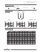
Generic Parts List Page 25 25 25
Generic Parts List Item 1 2 3 4 5 6 7 8 9 10 11 12 13 14 15 16 17 18 19 20 21 22 23 24 25 26 27 28 29 30 Item 31 32 33 34 35 36 37 38 39 40 41 42 43 44 45 46 47 48 49 51 52 53 54 55 56 57 58 59 Description T&P Relief Valve. Nipple Plastisert. Hot Water Outlet Nipple. Magnesium Anode. Nipple Galvanized. Pipe Tee Galvanized. Combination T&P Gage (optional). High Pressure Switch (optional). Low Pressure Switch (optional). Screw. Immersion Thermostat. Thermostat Dial. Hex Nut. Lock Washer. Screw.