
Service Manual


SEQUENCE OF OPERATION
Page 11
Certain other control components are available as “Optional“. These controls are specified when the installation has
unique requirements that must be safeguarded. When these optional components are installed the control circuit wiring
diagram accordingly will include these components. The optional equipment available from the manufacturer includes
the following:
High Water Pressure Switch
Low Water Pressure Switch
Low Water Level Switch
Alarm Horn
Heating Element Sequencers
Electrical Door Lock
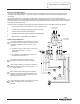
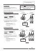
-Heating Element Sequencers are wired in series with
contactor coils staging contactor activation at
intervals of approximately 20 seconds.
Control Circuit Sequence (Continued)-
-Hi and Low Pressure Switch and Low Water Level Switch
when specified are always wired in series ahead of the
Hi-limit control.
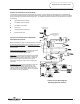
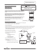
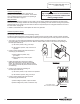
Control Circuit Sequence of Operation
with Optional Controls-
Control Circuit Wire Diagram
Showing Optional Controls
Line voltage from
power circuit
Same as explained on page 10 with the following exceptions:
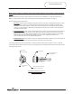
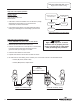
-Alarm Horn is wired in series ahead of the thermostat.
It monitors only the Hi and Low pressure switch, Low
water level Switch and the hi-limit (ECO). If either of
these switches open, power to the horn relay is
interrupted causing the relay to close sounding the
alarm horn.
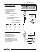
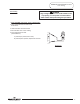
-Electrical Door Lock is wired in parallel to secure the
access to the water heater control cabinet. This
device will lock the control cabinet door when the
120VAC control circuit voltage is applied. Once the
door is opened, the water heater can be re-energized,
if necessary, for service diagnosis.
Appropriate line
voltage multi-tap
terminal
11
11