
Service Manual


SERVICE PROCEDURE ACE-VI
Contactor Testing
Contactor Operation Testing
Noisy or chattering contactor operation in most cases is due to voltage variations being supplied to the water heater.
Extended periods of voltage variations will cause damage to the operating coil of the contactor causing noisy operation.
Determine that service voltage to the unit meets the electrical requirements per the rating plate located on the front of
the water heater, see page 16
In addition, debris between the contact plates will cause noisy operation.
Noisy Contactor
This procedure assumes control circuit is operating correctly.
Providing the water temperature in tank is within the operating range of the thermostat, checking contactor operation
can be as simple as rotating the thermostat dial and listening to the contactor(s) to see if they respond to a call for heat.
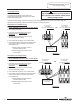
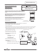
1. Turn Power “ON” and rotate thermostat dial to the maximum setting, with water temperature in tank below the
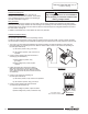
thermostat setting, the contactor(s) will close. With the contacts closed, check for 120 volts across operating coil
terminals (see illustration 8).
A) 120 volts IS present, okay, go to step 2.
B) 120 volts NOT present, verify control circuit
operation.
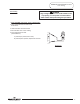
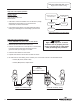
2. Check for rated voltage across lower terminals of
contactor(s) (see illustration 9).
A) Rated voltage IS present, okay,
go to step 3.
B) Rated voltage NOT present, replace
contactor.
3. Rotate thermostat dial to the minimum setting.
With water temperature in tank above thermostat
setting, the contactor(s) will open. With the contacts
open, voltage should not be present at lower terminals
of contactor(s).
4. Check for 120 volts across operating coil
terminals (see illustration 8).
A) 120 volts IS present, verify control circuit operation.
B) 120 volts NOT present, okay go to step 5.
5. Check for rated voltage across lower terminals
of contactor(s) (see illustration 9).
A) Rated voltage IS present, replace contactor.
B) Rated voltage NOT present, contactor is okay.
Page 20
DANGER
High voltage exposure. To avoid hazard to
life or property, use extreme caution when
making voltage checks .
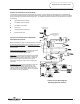
Illustration 8
Contactor operation is achieved by energizing an
operating coil located within the contactor. The contactor
coil is considered part of the control circuit operating at
120 volts as described on page 10.
Contactor Operating Coil
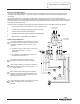
T1 T2 T3
L1 L2 L3
Check voltage across
lower terminals of contactor(s)
Illustration 9
20
20