STORAGE UNIT AST-40, AST-50, AST-80, AST-120 A Spanish language version of these instructions is available by contacting the manufacturer listed on the rating plate. La version espanola de estas instrucciones se puede obtener al escribirle a la fábrica cuyo nombre aparece in la placa de especificaciones. INSTALLATION & OPERATING INSTRUCTION MANUAL THE WARRANTY ON THIS STORAGE UNIT IS IN EFFECT ONLY WHEN THE STORAGE UNIT IS INSTALLED AND OPERATED IN ACCORDANCE WITH LOCAL CODES AND THESE INSTRUCTIONS.
TABLE OF CONTENTS General Information ..................................................... 3 Installation .................................................................... Locating The Storage Unit .................................... Water Connections ................................................ Electrical Connections .......................................... 4 4 6 9 General Operation ........................................................ 12 Thermostat Adjustment ..............................
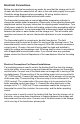
GENERAL INFORMATION This storage unit must be installed in accordance with local codes. In the absence of local codes, install this storage unit in accordance with the N.E.C. Reference Book (latest edition). The warranty for this storage unit is in effect only when the storage unit is installed, adjusted, and operated in accordance with these Installation and Operating Instructions.
INSTALLATION Locating The Storage Unit WARNING To avoid damage or injury, there shall be no materials stored against the storage unit and proper care shall be taken to avoid unnecessary contact (especially by children) with the storage unit. UNDER NO CIRCUMSTANCES SHALL FLAMMABLE MATERIALS, SUCH AS GASOLINE OR PAINT THINNER BE USED OR STORED IN THE VICINITY OF THIS STORAGE UNIT OR ANY LOCATION FROM WHICH FUMES COULD REACH THE STORAGE UNIT.
Locating the Storage Unit continued- This storage unit must be located in an area where leakage of the tank or water line connections and the combination temperature and pressure relief valve will not result in damage to the area adjacent to the storage unit or to lower floors of the structure. When such locations cannot be avoided, a suitable drain pan must be installed under the storage unit. The drain pan must have a minimum length and width of at least 4 in. (10.
Water Connections NOTE: BEFORE PROCEEDING WITH THE INSTALLATION, CLOSE THE MAIN WATER SUPPLY VALVE. After shutting the main water supply valve, open a faucet to relieve the water line pressure to prevent any water from leaking out of the pipes while making the water connections to the storage unit. After the pressure has been relieved, close the faucet. The fittings at the circulating connections and the hot water outlet are dielectric waterway fittings with tapered male pipe threads.
Water Connections continued- WARNING For protection against excessive temperatures and pressure, install temperature and pressure protective equipment required by local codes, but not less than a combination temperature and pressure relief valve certified by a nationally recognized testing laboratory that maintains periodic inspection of production of listed equipment or materials, as meeting the Requirements for Relief Valves and Automatic Gas Shutoff Devices for Hot Water Supply Systems, ANSI Z21.
Water Connections continued- WARNING Hydrogen gas can be produced in a hot water system served by this storage unit that has not been used for a long period of time (generally two weeks or more). Hydrogen gas is extremely flammable. To reduce the risk of injury under these conditions, it is recommended that the hot water faucet be opened for several minutes at the kitchen sink before using any electrical appliance connected to the hot water system.
Electrical Connections Before any electrical connections are made, be sure that the storage unit is full of water and that the manual shut-off valve in the cold water supply line is open. Check the wiring diagram before proceeding. All wiring shall be done in accordance with all applicable local and state codes. The thermostat incorporates a manual adjustable temperature indicator to change the potable water temperature.
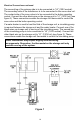
Electrical Connections continued- The second leg of the primary side is to be connected to “L2” (120V neutral). The secondary side of the transformer is to be connected to the zone valve coil. The contact side of the zone valve is to be connected to the boiler operating control. Connect the other black wire on the storage unit to “L1” (120V hot) (see figure 2). These connections enable the storage unit thermostat to control the zone valve and the boiler operating control.
Electrical Connections continued- Figure 2 Figure 3 11
GENERAL OPERATION CAUTION Scalding may occur within five (5) seconds at a temperature setting of 140°F (60°C). TO FILL THE STORAGE UNIT 1. Close the storage unit drain valve by turning the knob clockwise. 2. Open the cold water supply shut-off valve. 3. Open several hot water faucets to allow air to escape from the system. 4. When a steady stream of water flows from the faucets, the storage unit is filled.
Thermostat Adjustment continued- DANGER Hotter water increases the risk of scald injury. Scalding may occur within five (5) seconds at a temperature setting of 140°F (60°C). To protect against hot water injury, install an anti-scald tempering valve in the water system. This valve will reduce point of discharge water temperatures by mixing cold and hot water in branch water lines. A licensed plumbing professional or local plumbing authority should be consulted.
MAINTENANCE IMPORTANT The storage unit should be inspected at a minimum of annually by a qualified service technician for damaged components. DO NOT operate this storage unit if any part is found damaged. Shut off the electric power whenever the water supply to the storage unit is off. Shut off the electric power and water supply, drain the heater completely to prevent freezing whenever the building is left unoccupied during the cold weather months.
Maintenance continued- CAUTION FOR YOUR SAFETY, DO NOT ATTEMPT TO REPAIR THERMOSTAT, OR ELECTRICAL WIRING. REFER SUCH REPAIRS TO A QUALIFIED SERVICE TECHNICIAN. Contact your local plumbing supplier or plumbing professional for replacement parts or contact the company at the address displayed on the rating plate of the storage unit. For faster and better service, please provide the part name, model, and serial number(s) of the storage unit(s) when ordering parts.
PARTS LIST STORAGE UNIT 1 2 3 4 5 6 7 PART DESCRIPTION Thermostat 8 Nipple Thermostat Cover 9 Diptube (Cold Inlet) Thermostat Access Cover 10 Anode (Hot Outlet) Thermostat Mounting Temperature & Pressure 11 Bracket Valve (Not Provided) Plug 12 Electrical Junction Box Electrical Junction Box Plug Gasket 13 Cover/Conduit Connection Electrical Junction Box Drain/Return Valve 14 Cover 16
TYPICAL INSTALLATIONS 17
Typical Installations continued- 18
NOTES 19
NOTES 20