Installation and Operation Instructions Document 1447B Installation and Operation Instructions for Brute® Commercial Electric Boiler 30 kW - 300kW A S M H E NOTE: Retain this manual for future reference. FOR YOUR SAFETY: This product must be installed and serviced by a professional service technician, qualified in hot water boiler and heater installation and maintenance. Improper installation and/or operation could cause serious injury, property damage, or death.
Electric Hot Water Boiler BEB Series Installation & Operating Manual The BEB Series electric boiler has been specifically designed for closed loop hot water applications with an output temperature range of 40° F to 195° F, including radiant floor heat, water coil, and geothermal back up, commercial process or indirect potable hot water. This electric boiler has options for fixed set point outlet temperature, outdoor reset and 0-10VDC.
Table of Contents Specification Table 1 Dimensional Drawings 2 Handling & Storage 3 Placement & Mechanical Information 3 Installation Requirements 5 Electrical Installation Preparation 6 Power Feed 7 Low Voltage Controls 7 Ground Fault Detector Options 8 Additional Safety Control Options 8 Multiple Boilers, Same System 8 Dual Boilers/Dual System 8 Setup/Programming 9 Understanding the Product Display 9 Hardware Setup 11 Software Setup 12 System Setup 13 Sensor Calibration
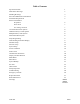
Specification Table Design Specifications Model Volts kW Total Amps Btu/h Output Amps 3Phase Feed #1† Feed #2† Flow Rate Element Quantity Steps @20° ∆T Required GPM Head Loss Boiler Weight FT M BEB-060-600X 600 60 58 204,729 58 – 5 5 @ 12 21 0.1 0.03 685 BEB-072-600X 600 72 70 245,675 70 – 6 6 @ 12 25 0.1 0.03 690 BEB-084-600X 600 84 81 286,620 81 – 7 7 @ 12 29 0.1 0.03 695 BEB-096-600X 600 96 93 327,566 93 – 8 8 @ 12 33 0.1 0.
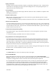
Dimensional Drawings 02/04/2021 2 BI810
Handling & Storage Receiving It is the receiver’s (person and/or company signing off on the receiving Bill of Lading) responsibility to inspect for shipping damage. All shipping claims must be made by the receiver. Verify receipt of a pallet. Storage This electric boiler, packed or unpacked, shall not be exposed to rain, snow, or other adverse environment. This product is designed for in-building storage and installation only.
Piping Connections The pipe extensions outside of the boiler cabinet are permanently welded to the vessel. Caution must be used to make sure field piping is properly threaded so damage does not result requiring field repair or a replacement (not under warranty) vessel. New Installation Piping connections and valves must comply with state and/or local codes, in addition to compliance with ANSI piping requirements.
Water Treatment Water treatment is strongly suggested to prevent scale deposits, corrosion from acids, oxygen, and other harmful elements within the specific water supply. It is the installer or user’s responsibility to verify water quality and maintain acceptable water quality throughout the life of this product. A qualified water treatment specialist should be consulted to establish proper water treatment program.
Electrical Installation – Preparation Typical external requirements – depending upon the electrical utility servicing the site, this model typically is added to the general service as a 3 Ø “Y” source. If the service is delta (unbonded neutral) with dedicated utility transformer, verify ground fault, a ground fault monitor may be required to maintain warranty. See nameplate and/or Specification Table for 3-phase operating voltage rating and kW rating to determine service entrance size.
Electric Installation – Power Feed Using the information from the previous section, it is the installer’s responsibility for proper 3-phase power feed and safety grounding per NEC and CEC electric codes. See Specification Table for distribution between the two feeder terminal blocks. Feed #1 always has 8 or less stages. Prepare service conductor cables and torque as required within the terminal block as required for the installer selected cable type and size.
Ground fault detector – BEB Series boilers are manufactured to utilize either of the two common 3phase electrical feeds: 3-Phase Y, with neutral and ground – the internal wiring configuration of the BEB boiler does not require a neutral. This unit is manufactured and shipped without ground fault protection. Certain state and local codes may require the addition of ground fault protection. Be certain to research and follow these codes.
Setup/Programming This boiler is supplied with a display. There are a multitude of setup functions on this display. Exhaustive research has been done to determine a “typical” application for the boiler. From the factory, this boiler is set to meet this typical application. Using the display, the Boiler can be reconfigured to meet your application. Understanding the Product Display The Boiler includes a 4-line OLED display with a set of navigation buttons.
Display Line 1, MODES If there is no active heat call to the Boiler, the OLED will display a mode of “OFF”. This means no heat is being generated from the heating system. Indicates there is a heat call requirement from the system thermostat. The Electric boiler portion of the heating system is receiving this input, and is actively working to heat the space. The stand by boiler is not active (if applicable). Only applicable when a backup fossil fuel boiler is connected to this Boiler.
Hardware Setup The boiler includes an outdoor sensor which is disconnected from the factory. Based on the condition of this outdoor sensor upon boiler power-up (connected or disconnected), the boiler will work to formulate its desired set point output temperature upon system thermostat demand in one of two ways: Connected: If the outdoor sensor is connected upon system power-up, the boiler will enable its outdoor reset function.
Software Setup Understanding System Setup and Configuration The display and configuration section of the display allows for system setup and calibration. NOTES: All changes made to the system will happen immediately. It is best not to make changes while the Boiler is actively operating (active heat call). Satisfy thermostat call before entering the setup up section of the display.
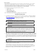
SYSTEM SETUP 02/04/2021 13 BI810
SYSTEM SETUP: SETUP / FAULTS: SET POINT: When operating this boiler in NON-outdoor reset mode (outdoor sensor not connected upon power-up), this value is the fixed set point output water temperature the boiler will try and achieve and maintain upon an active thermostat heat call.
DIFFERENTIAL: This is used to indicate to the logic board (non 0-10VDC mode) how tightly to maintain boiler target temperature. It must be noted that the lower the value used, the more boiler cycling will occur. This has direct relation to life span of the boiler contactors and other components. MAX STAGES: This is typically a factory setup screen, as the boiler is manufactured, we indicate to the logic board the amount of stages it has to work with (4 – 15 stages depending on boiler kW).
SENSOR CALIBRATION Use “ENTER” Button to increase value of digit selected. Use UP and DOWN buttons to move curser up and down Use LEFT and RIGHT buttons to move curser left and right OFFSET ST: If there is a need to calibrate the supply temperature sensor, enter in the desired offset. NOTE: The value entered is the offset, not sensor temperature. Pressing 075° will add 75° to the existing sensor reading. It will not cause the sensor to now equal 075°.
FAULT TRACKER Fault tracker is a read only function of the display. It allows you to view a history of the various faults for this boiler. You can clear / reset all faults by accessing the last screen in the string of screens. Press “YES” in the “CLEAR ALL” option will reset all to 0.
OUTDOOR RESET PARAMETERS 02/04/2021 18 BI810
OT @ 0°F SP: When operating this Boiler in outdoor reset mode (outdoor sensor connected upon powerup), set this value to your desired set point output water temperature when the outdoor temperature is 0°F. As the outdoor temperature fluctuates, the output water temperature desired with shift in an attempt balance the boiler output with the heat load requirement of the space. RANGE 40°F to 195°F.
DISPLAY VARIABLES DEFINED MULTI-BOILER BOILER: Enter the role this boiler will play in the heating system. Options: SINGLE: This indicates there are no other Boilers in this application. It will not attempt to interface with another boiler that does not exist. LEAD: This indicates that there is another Boiler in this application. LEAD setting tells this boiler that it is the lead boiler and it is in control of an external boiler. The LEAD boiler will control all LEAD / LAG sequencing.
MICRO RESET Certain setting changes made by display require a reset of the microcontroller. A power down reset of the boiler is an option, otherwise you can select to reset the microcontroller via this software selection.
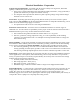
SYSTEM HOOKUP PRIMARY APPLICATION WITH LMC SYSTEM HOOKUP PRIMARY APPLICATION WITHOUT LMC 02/04/2021 22 BI810
SYSTEM HOOKUP LEAD LAG BOILER NOTE: If system has LMC, both LMC circuits need to be controlled via isolated end switches (field supplied). If not using LMC, leave factory jumpers in place.
SYSTEM HOOKUP SENSORS 02/04/2021 24 BI810
Pre-Start General inspection – inspect all components, external and internal to assure there has been no damage during shipment or installation. Verify proper cabinet clearances on both sides and top and the internal is free of construction dirt and debris. Blowing out with an air hose is suggested. Verify all electrical connections are properly tightened and correct.
Temperature limits information – there are three temperature sensing monitors which will control the sequencer and electric elements. The control main control board, with its supply sensor, controls the stages to maintain a supply temperature represented by system configuration. This sensing monitor and control applies to outdoor reset or no outdoor reset. Auto reset limit, HL-2 – probe at the vessel top, fixed at 210° F (99° C), signals sequencer to shut down (auto resets at approximately 195° F (90.
Startup Inspection Comment – the words “power service” or “power source” refer to the 480/208/240 3-phase source dedicated to the electric elements. 1. All main unit staging CB’s should be off. The dead front inside panel is still probably off; this is okay because the installer needs to check the source voltage. The panel interlock switch is open thus contactors cannot pull in. 2. Verify the control box 120 CB is off and R to W input is open or off. 3.
Troubleshooting Power Source Electric element supply – the boiler vessel elements are fed from the main unit inside terminal block. Depending upon model number and configuration this may require 480, 208, or 240 3-phase. See Specification Table for specific installation requirement. This boiler is designed and wired for a Delta electric element load arrangement.
Faulty sensor default – the OLED display indicates a sensor issue, but the boiler continues to function based upon a fixed default temperature within the logic. RT sensor – no default, this is not critical OT sensor – this is only active when outdoor sensor connected during power-up.
Emergency Override If this is not a dual boiler installation and in case of an absolute necessity to maintain building heat or freeze-up, the service technician or maintenance technician can consider rewire and manually operate the Sequencers. CAUTION WHEN OVERRIDING THE BUILT-IN CONTROLLERS IN THE FOLLOWING STEPS, ALL ALARM LIMITS ARE STILL ACTIVE AND WITHIN THE CONTROL CIRCUITRY. IT IS STRONGLY RECOMMENDED NO FURTHER BYPASS BE CONTEMPLATED OR USED IN ORDER TO MAINTAIN PROPER SAFETY.
Replacement Parts Part Number Description Part Number Description 1 L5683 Circuit Breaker, 30-amp, 3 Pole, 480V ETA 13 L5539 High Limit, Auto Reset 210° F 1 L5685 Circuit Breaker, 50-amp, 3 Pole, 480V ETA 14 L5531 High Limit, Manual Reset 220° F 1 LUFH6645 Fuseholder, 30-amp, 3 Pole, 600V models only 15 LUSW1145 Door Safety Switch Power Panel 1 LUFUSE6650 Fuse, 30-amp, 600V models only 16 LULAMP2289 Indicator Light Green, 125VAC 2 LEBNTB5669 Main Control Board 17 L5086 Term
Boiler Maintenance The boilers are designed to give years of worry free service. Just like any other piece of mechanical heating equipment they require annual inspection and maintenance for optimal performance. Improper maintenance and missed inspection can lead to such issues as wire connection failure, electrical component failure, excessive noise, and element failure. CAUTION ALWAYS DISCONNECT ELECTRIC POWER FROM BOILER BEFORE PERFORMING MAINTENANCE. 1.
DISPLAY
Brute Commercial Electric Boiler Notes: 200 Lafayette St. Middleville, MI 49333 (800) 523-2931 www.BradfordWhite.com Litho in U.S.A.