
Installation / Operation Instruction Manual

02/04/2021 7 BI810
Electric Installation – Power Feed
Using the information from the previous section, it is the installer’s responsibility for proper 3-phase
power feed and safety grounding per NEC and CEC electric codes.
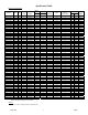
See Specification Table for distribution between the two feeder terminal blocks. Feed #1 always
has 8 or less stages.
Prepare service conductor cables and torque as required within the terminal block as required for
the installer selected cable type and size.
Some local codes and CEC electric code require single disconnect and single feed. If this is the case,
installer must provide disconnect with multiple feeds per drawing BH802.
Electrical Installation – Control Box
120, single phase, 15A general service or main building service panel source – provide and route to
the upper left corner CB and neutral block.
Note: A green wire ground from this general service panel is not required or suggested because the ground
lug within the control box is connected to the main safety ground in the main unit. Based upon grounding
details in the Electrical Installation – Preparation section, the main unit ground lug is bonded to the
building grounding electrode system.
Boiler heat call R-W – there must be a contact closure between R and W to activate this boiler. This can
be a thermostat heat call, end switch or building control signal.
If operating as a hot boiler with continuous pump, typically a system on/off switch controls the R
and W. Provisions need to be made to make sure it is continuous pump, suggest with this
arrangement a flow switch is connected in this R and W contact loop.
Boiler heat call 0-10VDC operation – when the Laars boiler is configured through the boiler control
panel to operate on a 0-10VDC signal, the facility boiler control signal must include both the 0-10VDC
signal to terminal T7 (0-10VDC in) and a contact closure across the R-W terminal. The 0-10VDC will not
function unless R-W is closed. If a jumper is placed across R-W, precautions must be made to ensure the
system pump is active whenever a 0-10VDC signal is present at the boiler. This is to prevent elements
from activating with no flow and prevent tripping of the manual high limit.
Main circulating pump – determine whether pump is continuous on or is operated by the R to W input
signal, use the pump relay (the larger cube relay) on the board. When using the top two terminals this has
a 25-amp, 120V or 240V, rating. Route and clearance protect these line voltage wires in and out of the
control box as required by NEC/CEC code. This contact can be used to drive an external contactor for 3-
phase or higher voltage pumps.
LMC or utility load control – if this is a required part of this installation, remove the blue jumper at the
LMC terminal and route two wires to the utility load receiver normally closed contact. The electric boiler
elements are disabled when this circuit is open.
External Alarm – a set of dry contacts, “EXT Alarm”, provide a contact closure for remote alarm
monitoring. These contacts will close on a low water cut off alarm, manual high limit, or boiler sensor
fault. These are all conditions that require physical inspection of the boiler to solve the issue.
Outdoor sensor (OT) – this product is factory shipped with a 25’ (7.6 meter) cable and OT sensor. It has
three tabs on the board, bottom left. From the factory, this sensor is shipped loose. If the outdoor sensor is
required for the application, simply connect the sensor to the board (power cycle required).
Note wire colors and labeling, sensor cable can be disconnected for installation. Do not route OT sensor
cable along line voltage Romex or line voltage wiring (crossing is okay when there is a somewhat parallel
route). Sensor box must be installed in a location out of direct sunlight. Sensor box should also be
mounted high enough off the ground to prevent being covered with snow or ice.