Installation and Operation Instructions Document 1490B Installation and Operation Instructions for Brute Mini ® Residential Gas-Fired Hydronic Boilers Sizes 50-200 MBTU/h FOR YOUR SAFETY: This product must be installed and serviced by a professional service technician, qualified in hot water boiler and heater installation and maintenance. Improper installation and/or operation could create carbon monoxide gas in flue gases which could cause serious injury, property damage, or death.
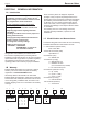
BRADFORD WHITE TABLE OF CONTENTS SECTION 1 GENERAL INFORMATION 1.A Introduction.............................................. 4 1.B Warranty.................................................. 4 1.C Model Number and Nomenclature.......... 4 1.D Safety Warnings...................................... 5 1.E Model Overview....................................... 6 1.F Pressure Gauge...................................... 8 1.G Digital Dashboard.................................... 8 1.H The Installation Kit..........
Brute Mini ® RESIDENTIAL BOILERS 8.B Advanced Programing........................ 32 8.B.1 Fahrenheit or Celsius............................ 32 8.B.2 Low Water Cut-Off................................. 32 8.B.2.a RESET, Manual or Automatic................ 32 8.B.2.b Testing Low Water Cut OFF.................. 33 8.B.3 High Limit Differential............................ 33 8.C Sensor Programming.......................... 33 8.C.1 Outdoor Sensors................................... 33 8.C.
BRADFORD WHITE Page 4 SECTION 1 GENERAL INFORMATION 1.A Introduction Some accessory items are shipped in separate packages. Verify receipt of all packages listed on the packing slip. Inspect everything for damage immediately upon delivery, and advise the carrier of any shortages or damage. Any such claims should be filed with the carrier. The carrier, not the shipper, is responsible for shortages and damage to the shipment whether visible or concealed.
Brute Mini ® Page 5 RESIDENTIAL BOILERS 1.D Safety Warnings Safety Warnings are used throughout this manual to bring attention to the presence of hazards with various risk levels and to offer important information concerning the life of this product. There are 3 basic types. 1 WARNING 2 CAUTION 3 Indicates an imminently hazardous situation which, if not avoided, can or will result in death or serious injury and can or will result in catastrophic property damage.
t de n BRADFORD WHITE Page 6 1.D Safety Warnings (continued) WARNING Electrical Shock Hazard WARNING The Repair Parts list designates parts that contain refractory ceramic fibers (RCF). RCF has been classified as a possible human carcinogen. When exposed to temperatures above 180ºF, such as during direct flame contact, RCF changes into crystalline silica, a known carcinogen.
Brute Mini 1.E Page 7 RESIDENTIAL BOILERS ® Model Overview (continued) Hydronic Return Hydronic Supply Vent Damper Low Loss Header (sizes 125 - 200) Pressure Gauge The Digital Dashboard Panel Lock See 8.A on page 30 Drain Rating Plate Pressure Relief Valve ‘Knock-outs’ Gas Supply Pressure Relief Valve Main Power 120V Connections See 7.B on page 23 Gas Supply DHW Relay Connections TB3 Field Connections TB1 Field Connections TB2 See 7.D on page 24 Gas Valve Pilot Ignitor Sensor Figure 3.
BRADFORD WHITE Page 8 1.F Pressure Gauge The Pressure gauge is installed just above the Digital Dashboard. The pressure is sensed at the top front section of the inlet/outlet header. Figure 4. System Pressure 1.G Digital Dashboard The Digital Dashboard displays the boiler's status while it is running.
Dimensional Brute Mini Data ® 1.
BRADFORD WHITE Page 10 SECTION 2 LOCATING THE BOILER 2.A Field Assembly This boiler is shipped with an automatic vent damper that must be assembled onto the vent collar on the top of the boiler, and then plugged into the unit using the dedicated harness. 2.B Boiler Placement This boiler is design certified by CSA-International for indoor installation on combustible flooring, in basements, in closets, utility rooms or alcoves. These units must never be installed on carpeting. 1.
Brute Mini ® SECTION 3 Page 11 RESIDENTIAL BOILERS Air and Venting 3.A Safety Warnings WARNING This boiler must be vented in accordance with Part 7, Venting of Equipment, of the latest edition of the National Fuel Gas code, NFPA 54/ANSI Z223.1 and all applicable local building codes. In Canada, follow CAN/CSA B149.1 Installation codes.
BRADFORD WHITE Page 12 3.B Combustion Air Supply The boiler location must provide sufficient air supply for proper combustion, and ventilation of the surrounding area as outlined in the latest edition of U.S. ANSI standard Z223.1 or in Canada, CAN/CSA-B149.1 and any local codes that may be applicable.
Brute Mini Page 13 RESIDENTIAL BOILERS ® 10 (3.0) OR LESS 2 (0.6) MIN. WALL OR PARAPET CHIMNEY 10 (3.0) OR LESS 2 (0.6) MIN. RIDGE MORE THAN 10 (3.0) 3 (0.9) MIN. 3 (0.9) MIN. TERMINATION 10 FT. (3.0m) OR LESS FROM RIDGE, WALL OR PARAPET 3 (0.9) MIN. CHIMNEY WALL OR PARAPET NOTE: NO HEIGHT ABOVE PARAPET REQUIRED WHEN FROM WALLS OR PARAPET IS MORE THAN 10 FT. (3.0m) Dimensions in feet (m). CHIMNEY MORE THAN 10 (3.0) 10 (3.0) RIDGE 2 (0.6) MIN. 3 (0.9) MIN. CHIMNEY Figure 9.
Page 14 3.D Vertical Venting - Category I All venting must comply with fuel gas code and be installed by a licensed installer. This boiler can be vented into a masonry chimney, (see Figure 7 and Figure 8 on page 12) provided several conditions are met: 1. The chimney must have an appropriate lining that is clean, properly constructed and properly sized. 2. The chimney passage way shall be examined to ascertain that it is clear and free of obstructions. 3.
Brute Mini ® Page 15 RESIDENTIAL BOILERS 3.E Locations for Vent Pipe Terminator Canadian Installations1 U.S.
BRADFORD WHITE Page 16 3.F Venting with a Power Venter This boiler is certified for use with the manufacturer's suggested Power Venter, which is supplied in a kit that includes Installation Instructions. See the accessories list in the Parts Section of this manual. The location of the venter on the outside wall shall be in accordance with ANSI Z223.1/NFPA 54, or in Canada with CAN/ CSA-B149.1 and applicable local codes. 3.
Brute Mini RESIDENTIAL BOILERS SECTION 4 Gas Connections ® Page 17 4.A Gas Supply and Piping Follow this guideline checklist for the gas supply installation. 1. Gas piping installation must be in accordance with the latest edition of ANSI Z223.1 and all local codes. In Canada, the installation must be in accordance with CSA-B149.1 and all local codes that apply. Supply Pressure Natural Gas LP Gas Table 3. Minimum 5.5 Inches WC Maximum 10.5 Inches WC (1.4 kPa) (2.6 kPa) 10.0 Inches WC 13.
BRADFORD WHITE Page 18 NOTE: The boiler and all other gas appliances sharing the boiler gas supply line must be firing at maximum capacity to properly measure the inlet supply pressure. Low gas pressure could be an indication of an undersized gas meter and/or obstructed gas supply line. 8. 9. 10. The correct manifold gas pressure is stamped on the rating plate. The regulator is pre-set at the factory, and normally requires no further adjustment.
Brute Mini ® SECTION 5 125 125 36.6 105 31.1 91 26.7 84 1-1/4 3/4 150 150 44.0 126 37.2 110 32.2 84 1-1/4 3/4 176 3/4 206 200 199 58.3 168 146 49.2 RESIDENTIAL BOILERS 84 42.8 1-1/4 Note: The Net AHRI Water Ratings shown are based on a piping and pickup allowance of 1.15. *Add approximately 9 Lbs for unit with pump. 202 237 Page 19 PUMP REQUIREMENTS This boiler has a water tube design, and requires NOTE: Field Supply System / Zone pump(s) for all models.
BRADFORD WHITE Page 20 SECTION 6 WATER CONNECTIONS 6.A Water Piping NOTE: This boiler must be installed in a closed pressure system with a minimum of 12 psi (82.7kPa) static pressure at the boiler. Section 6.D on page 21 shows typical plumbing installations. Be sure to provide unions and isolation valves at the boiler inlet and outlet so it can be isolated for service. Check local codes for specific plumbing requirements before beginning the installation.
Brute Mini ® Page 21 RESIDENTIAL BOILERS 6.D Typical Plumbing Diagrams These diagrams are only meant as a guide. All components or piping required by local code must be installed.
BRADFORD WHITE Page 22 Typical Plumbing Diagrams (continued) Check Valves Air Scoop Valves Drains Zone Pumps (must be sized properly) Pump Valves Valves Check Valve Low Loss Header w/ Pump Indirect Tank Boiler JX Figure 16. Low Loss Header with Zone Pumps and DHW Low Loss Header is standard on models 125, 150, and 200 and Optional for models 50, 75, and 100.
Size Natural Gas MBTU/h kW MBTU/h kW AFUE % % 42 12.6 37 10.8 84 RESIDENTIAL BOILERS 75 75 22.0 63 18.8 55 16.1 84 100 100 29.3 84 24.9 73 21.4 84 125 125 7 36.6 ELECTRICAL 105 31.1 91 84 SECTION AND26.7WIRING 150 150 44.0 126 37.2 110 32.2 84 7.A Safety Warnings 200 199 58.3 168 49.2 146 42.8 84 50 50 MBTU/h kW 14.
BRADFORD WHITE Page 24 7.D Field Connections This boiler has three Field Connection Terminals. TB1, TB2 and TB3 (TB3 is for optional equipment). Open TB2 - 120 VAC Outputs Closed TB3 -DHW Relay Connections (optional) TB1 -TT, DHW, OAS Figure 19. Unlocking the Cover Figure 18. Terminal Block Locations 7.D.1 WARNING TB1 (Terminal Block 1) TT, DHW, OAS No Power to be applied to terminals 10-12 of TB1. Sensor Connections Only! 7.D.1.
Brute Mini ® 7.D.2 Page 25 RESIDENTIAL BOILERS Pump contacts rated to 5.8 FLA. TB2 (for pumps and aux power) 7.D.2.a Boiler Pump This terminal and the 120V(N) terminal will provide power to the boiler pump whenever the boiler is running. Use this to power the Low Loss Header (LLH) pump or a boiler pump in a Primary/Secondary application. If not using a LLH then this terminal can run power for a single zone or a zone valve system pump. 7.D.2.b SYS Pump Figure 21.
BRADFORD WHITE Page 26 7.E Wiring Connections, Power Vent and Air Example: Laars Power Vent Kit Wiring to JX Terminals 2 and 3 are both 120V Neutral TB1 120 VAC 24 VAC Figure 23. Power Vent Kit Wiring example Example: Fields Controls CAS-4 Wiring to JX WARNING Example: Fields Controls CAS-4 Wiring to JX No Power to be applied to terminals 10-12 of TB1.
Example: Typical Zone Valve Control Wiring to JX for An�-condensing protec�on. Brute Mini ® Page 27 RESIDENTIAL BOILERS TB1 L N 1 2 4 Laars Power Vent Kit of the Zone Valves should not NOTE: The total power requirement 24 V Field Wiring. exceed the total capacity of the transformers.
BRADFORD WHITE Page 28 7.
Brute Mini Page 29 RESIDENTIAL BOILERS ® 7.G Logic Diagram WARNING TB1 No Power to be applied to terminals 10-12 of TB1.
BRADFORD WHITE Page 30 SECTION 8 HE DIGITAL T DASHBOARD 8.A Getting to know the Digital Dashboard. NOTE: Most installations will not require setting anything within the Digital Dashboard. The reasons for lifting the small transparent cover and adjusting the control are: - Setting the low water cut-off to manual reset. - Adjusting high limit to anything other than 190°F / 88°C. - Installing an outdoor sensor for the purpose of setting the Reset Curve.
Brute Mini ® Decimal lights on a call for heat. RESIDENTIAL BOILERS Control, Digital and Ignition L E D s Page 31 For full details, See Section 8.A.5 on page 31 The Ignition LED’s light in sequence Mode LEDs light in sequence. ECONOMY Settings LO LIMIT HI LIMIT Carbon monoxide hazard. The vent damper must(WWSD be fully open fluemore) must be clear Curveand Adjthe -and (Adv Programing) (Program Select) before the main burner fires.
BRADFORD WHITE Page 32 8.A.7 Ignition LEDs 8.A.7.a LIMITS See Figure 32 Illuminates on a call for heat to indicate the limits are satisfied. Limits may include flame rollout, spill switch, field interlock terminals (secondary low water cutoff etc). If the limits are open the LED will blink. Mode 8.A.7.b V-PWR Figure 33. Advanced Programing Indicates power has been sent to the vent damper. The damper will open causing its end switch to close. 8.A.7.
Setting Brute Mini ® RESIDENTIAL BOILERS Fahrenheit or Celsius Dial Setting The manual reset feature meets CSD-1 requirements. If in the Manual Mode, the control can only be reset by pushing the Mode button. To activate Manual Reset LWCO mode. 1. Turn the Advanced Programing dial to access the Program Mode – indicated in the display as Pro. 2. Turn the HI LIMIT dial to select feature 3. 3. Push the Mode button to A for Automatic Reset. See Table 8. Mode or b (lower case b) for Manual Reset Mode. 4.
BRADFORD WHITE Page 34 To set the desired warm weather shutdown temperature: Press and hold the Mode button and simultaneously adjust the ECONOMY dial to the desired temperature setting. To turn warm weather shutdown off - which will allow space heating regardless of outdoor temperature press and hold the Mode button and simultaneously turn the ECONOMY dial fully counter-clockwise. Release the Mode button. After doing this, be sure to reset the ECONOMY dial to the correct setting.
Brute Mini ® Page 35 RESIDENTIAL BOILERS 8.E View Current Settings Example: If the thermostat is not satisfied thirty down. The boiler water will continue circulate and heat the The Mode button has several to functions when minutes after the boiler the reset temperature, TEMP ACTIVE Indicates that the reaches Fuel Smart house as long as the thermostat call continues. The LED programing the boiler.
M BRADFORD WHITE Page 36 SECTION 9 INITIAL STARTUP 9.A Filling the System It is crucial to the efficient operation of the system that all air be removed from the circuit. For this reason, an air scoop and vent should be located close to the boiler outlet, and there should be a minimum distance between cold water feed and air elimination system. 1. When the system has been completely installed, and is free of leaks, open all automatic air vents and close all manual vents. Open the makeup water valve.
Brute Mini ® Page 37 RESIDENTIAL BOILERS NOTE Always test for a complete electrical system ground. High voltage ignition can cause electrical interference if not properly grounded. WARNING Electrical shock hazard. The ignition circuit of the control can produce over 10,000 volts which can cause severe injury or death. NOTE: Check for good quality pilot flame. See Section 9.C on page 38. NOTE: Check the flame current and make the necessary adjustments to the pilot valve. See Section 9.C on page 38.
BRADFORD WHITE Page 38 9.C Proper Pilot Flame To view the pilot flame, the cover must be unlocked and removed. A properly adjusted pilot should have a blue, steady flame with an inner cone that engulfs 3/8” - 1/2” of the pilot ignitor sensor. See Figure 45 The pilot ignitor sensor should glow bright orange from the heat and the flame current should be 1.0 μA to 1.8 μA. Open Closed NOTE: To read flame current see Section "8.
Brute Mini ® Page 39 RESIDENTIAL BOILERS FOR YOUR SAFETY READ BEFORE OPERATING 9.D L ighting Instructions Decal Lighting instructions are located on a label on the right side of the boiler, and are depicted in this section of the manual. For details on starting this boiler and what the digital dashboard is showing you as the boiler is started, please see Sections 8.A on page 30 and 9.
BRADFORD WHITE Page 40 9.E System Shutdown 1. 2. 3. Turn off the main electrical disconnect switch. Close all manual gas valves. These boilers are certified for indoor use only and should not be subjected to freezing temperatures. When shutdown or during and extended power outage, component failure or other condition when freezing is likely, the boiler and system must be drained. To completely drain the boiler, • First drain the right side by opening the boiler drain.
Brute Mini ® 10.A.3 RESIDENTIAL BOILERS Side Panel Removal Remove the front access and the top as described previously. Drain the boiler and remove the drain valve and/or the PRV and associated fittings depending on the panel being removed. Then pull upward and inward slightly at the top inside flanges. These are spring type latches which will release as force is applied upward.
BRADFORD WHITE Page 42 10.B Maintenance WARNING The Warranty does not cover damage caused by lack of required maintenance, lack of water flow, or improper operating practices. AVERTISSEMENT La garantie ne couvre pas les dommages causés par l'absence d'entretien, absence de débit d'eau, ou pratiques de fonctionnement irrégulières 1. L ubricate any motor bearings that are not sealed bearings per the instructions. 2.
Brute Mini ® Page 43 RESIDENTIAL BOILERS SECTION 11 Operating Details and Troubleshooting 11.A Operating Details When power is turned on, the digital display will indicate the boiler outlet temperature. If a demand for heat is received from a room thermostat or a tank aquastat (if provided) the third decimal LED, located at the lower right of the last temperature digit, will illuminate to indicate that a call for heat has been received and the startup has been initiated. See Section 9.B for details.
BRADFORD WHITE Page 44 11.C Troubleshooting Table # Symptom Cause Remedy 1 Boiler Pump not operating No power. Pump defective. Incorrectly wired. Check circuit breakers and power source. Replace. Recheck wiring diagrams (System pump will not work if below 160ºF or if DHW call) 2 Pilot outage Inlet gas pressure too low. Consult gas utility company. Inlet gas pressure to boiler should be 5.5" (1.4 kPa) to 10.5" (2.6 kPa) water column on natural gas. 10.0" (2.5k Pa) to 13.0" (3.
Troubleshooting Chart 1BOILERS – Burner Will Not Fire RESIDENTIAL Brute Mini Flow Page 45 ® 11.D Troubleshooting Flow Charts 11.D.1 Is the Green LED (TEMP ACTIVE) On? roubleshooting T Flow Chart 1 (burners off) The Temp Active LED will be on at all times when the control is powered. The Control is Not Powered. NO Check for 120 VAC on the control input. Check for 24 VAC to the board.
Check vent damper, end switch, and check TB1, PV1 + PV4 should be closed by a jumper or a switch from an external power vent kit or combustion air end switches. Replace Control Page 46 from BRADFORD WHITE previous page NO YES roubleshooting Flow T Chart 1 (burners off) (continued) Is There 24 VAC on the PV terminal of the Valve? YES Is there spark at the pilot? Is the Pilot Lit? NO YES Check gas pressure to the pilot. Clean or replace pilot orifice.
Brute Mini ® RESIDENTIAL BOILERS Page 47 11.E Glossary of Terms Air Vent A device used to purge air from the circuit. It should be located at the highest point in the circuit. Temperature Controllers The primary temperature controller maintains all normal heating operations. Auto-Reduce Reduces 5 degrees with every new call Reduces 5 degrees every 30 minutes of no demand.
BRADFORD WHITE Page 48 SECTION 12 REPLACEMENT PARTS 12.
Brute Mini Page 49 RESIDENTIAL BOILERS ® A7 A1 A8 A2 D4 A3 A9 A5 A10 A4 B6 A6 B7 B4 A17 B8 A16 D1 B2 B9 B1 D2 D13 B5 C1 B4 C2 B3 C5 C4 C6 C3 D3 A15 A14 A13 A12
Pilot Pilot orifice orifice (Nat) (Nat) 2001-10,000' 2001-10,000' W2002200 W2002200 W2002200 W2002200 W2002200 W2002200 W2002200 W2002200 W2002200 W2002200 W2002200 W2002200 C2C2 Main Main Gas Gas Valves Valves Pilot Assembly (Natural) R0061600 R0061600 R0061600 R0061600 R0061600 R0061600 Gas Gas Valve, Valve, (Natural) (Natural) RV2030700 RV2030700 RV2030700 RV2030700 RV2030700 RV2030700 RV2030700 RV2030700 RV2030700 RV2030700 RV2030700 RV2030700 W2001700 W2001700 W2001700 W2001700 BRADFORD W2001700 W W20017
Brute Mini Page 51 RESIDENTIAL BOILERS NOTES: 1. E2393900 IN 2. E0102000 IN AND TB1:8A D1 B9 REV SH D2 THIS DOCUMENT AND THE INFORMATION CONTAINED HEREIN ARE PROPRIETARY TO LAARS HEATING SYSTEMS AND SHALL NOT BE REPRODUCED, TRANSFERED TO OTHER DOCUMENTS, USED OR DISCLOSED TO OTHERS FOR MANUFACTURING OR ANY OTHER PURPOSE EXCEPT AS SPECIFICALLY AUTHORIZED IN WRITING BY LAARS HEATING SYSTEMS.
Brute Mini ® RESIDENTIAL BOILERS Notes: H2413300B Dimensions and specifications subject to change without notice in accordance with our policy of continuous product improvement. 200 Lafayette St. Middleville, MI 49333 Warranty: (800) 531-2111 www.BradfordWhite.com Litho in U.S.A.