
Installation / Operation Instruction Manual


Page 10
BRADFORD WHITE CORP
.
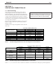
Table 4. Vent / Air Pipe Sizes
Vent System
Vent System
INTAKE / EXHAUST
Max Equivalent
*
Vent and Air Pipe Length (each)
STANDARD OPTIONAL
Size 2" dia 5.1cm 3"/5" dia 7.6/12.7cm
125 40 ft 12.2m 40 ft 12.2m
Installations in the U.S. require exhaust vent pipe that is PVC or CPVC complying
with ANSI/ASTM D1785 F441 or stainless steel complying with UL1738. Laars
suppliestherstsectionofventpipewhichis16"ofCPVCwitheachboiler.Installa-
tionsinCanadarequireexhaustventpipethatiscertiedtoULCS636.
Intake (air) pipe may be PVC, CPVC, ABS or galvanized pipe.
*
To calculate equivalent length, measure the linear feet of the pipe, and add 5 feet
(1.5m) for each elbow used.
INTAKE AND EXHAUST LENGTH
MAX EQUIV. MAX EQUIV. CONCENTRIC MAX EQUIV.
SIZE VENT FT. M VENT FT. M VENT FT. M
50 2" 40 6.1 *3"* 150 30.5 3/5" 40 6.1
75 2" 40 6.1 *3"* 150 30.5 3/5" 40 6.1
100 2" 40 6.1 *3"* 150 30.5 3/5" 40 6.1
125 2" 40 6.1 *3"* 150 30.5 3/5" 40 6.1
150 2" 40 6.1 *3"* 150 30.5 3/5" 40 6.1
175 2" 40 6.1 *3"* 150 30.5 3/5" 40 6.1
220 2" 30 4.6 *3"* 120 24.4 3/5" 40 6.1
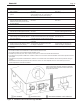
INTAKE / EXHAUST
Max Equivalent Vent and Air Pipe Length (each)
STANDARD 2-PIPE STANDARD 2-PIPE OPTIONAL CONCENTRIC
SIZES DIA. FT. m DIA. FT. m DIA. FT. m
50 - 175 2" 40 12.2 *3"* 150 45.7 3/5" 40 12.2
220 2” 30 9.1 *3”* 120 36.6 3/5” 40 12.2
Installations in the U.S. require exhaust vent pipe that is a combination of PVC & CPVC complying with
ANSI/ASTM D1785 F441 or stainless steel complying with UL1738. Polypropylene installations require
exhaustventpipethatiscertiedtoULCS636.
Intake (air) pipe may be any material that complies with ANSI/ASTM D1785 F441, ABS that complies with
ANSI/ASTM D1527 or galvanized material.
Installer must comply fully with manufacturer's installation instructions, to maintain ANSI Z21.13 safety
certication.
Closet and alcove installations do not allow the use of PVC under any circumstances
To calculate max equivalent length, measure the linear feet of the pipe, and add 5 feet (1.5m) for each
elbow used.
* Must use 2x3 adapter within 1 ft. (30cm) of boiler.
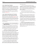
Electrical
Data
Size Boiler
Volts Phase Amps
MLX 50 120 Single 1.5
MLX 75 120 Single 1.5
MLX 100 120 Single 1.5
MLX 125 120 Single 1.5
MLX 150 120 Single 1.5
MLX 175 120 Single 2.2
MLX 220 120 Single 2.2
*
Minimum 15A circuit required
* Must use 2x3 adapter within 1 ft. (30cm) of boiler.
Reference the Installation and Operation Manual for more details.
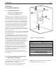
Bradford White Brute LX includes a standard CPVC vent/
combustionairadapter.Ifeldconnectionsrequireuseof
PVC/CPVC vent materials, the installer must use proper
adhesivetojoinCPVCand/orPVCpipeandttings.
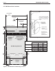
3.2 Combustion Air
Brute LX boilers and water heaters must have provisions
for combustion and ventilation air in accordance with the
applicable requirements for Combustion Air Supply and
Ventilation in the National Fuel Gas Code, ANSI Z223
1; or in Canada, the Natural Gas and Propane Installation
Code, CSA B149.1. All applicable provisions of local
building codes must also be adhered to.
A Brute LX unit can take combustion air from the
space in which it is installed, or the combustion air
can be ducted directly to the unit. Ventilation air must
be provided in either case.
3.2.1 Combustion Air from Room
In the United States, the most common requirements
specify that the space shall communicate with the
outdoors in accordance with method 1 or 2, which follow.
Where ducts are used, they shall be of the same cross-
sectional area as the free area of the openings to which
they connect.
Method 1: Two permanent openings, one commencing
within 12" (300mm) of the top and one commencing
within 12" (300mm) of the bottom, of the enclosure
shall be provided. The openings shall communicate
directly, or by ducts, with the outdoors or spaces
that freely communicate with the outdoors. When
directly communicating with the outdoors, or when
communicating to the outdoors through vertical ducts,
each opening shall have a minimum free area of 1
square inch per 4000 Btu/hr (550 square mm/kW) of
total input rating of all equipment in the enclosure.
When communicating to the outdoors through
horizontal ducts, each opening shall have a minimum
free area of not less than 1 square inch per 2000 Btu/
hr (1100 square mm/kW) of total input rating of all
equipment in the enclosure.
Method 2: One permanent opening, commencing
within 12" (300mm) of the top of the enclosure, shall
be permitted. The opening shall directly communicate
with the outdoors or shall communicate through a
vertical or horizontal duct to the outdoors or spaces
that directly communicate with the outdoors and shall
have a minimum free area of 1 square inch per 3000
Btu/hr (734 square mm/kW) of the total input rating of
all equipment located in the enclosure. This opening
must not be less than the sum of the areas of all vent
connectors in the conned space.