
Installation / Operation Instruction Manual


Page 29
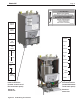
Brute LX
SECTION 7.
Electrical Connections
WARNING
The appliance must be electrically grounded in
accordance with the requirements of the authority having
jurisdiction or, in the absence of such requirements, with
the latest edition of the National Electrical Code, ANSI/
NFPA 70, in the U.S. and with latest edition of CSA
C22.1 Canadian Electrical Code, Part 1, in Canada. Do
not rely on the gas or water piping to ground the metal
parts of the boiler. Plastic pipe or dielectric unions may
isolate the boiler electrically. Service and maintenance
personnel, who work on or around the boiler, may be
standingonwetoorsandcouldbeelectrocutedbyan
ungrounded boiler. Electrocution can result in severe
injury or death.
Single pole switches, including those of safety controls
and protective devices must not be wired in a grounded
line.
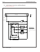
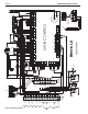
All electrical connections are made on the terminal
blocks that are located inside the control panel.
NOTE: All internal electrical components have been
prewired. No attempt should be made to connect
electrical wires to any other location except the terminal
blocks.
CAUTION
Label all wires prior to disconnection when servicing
controls. Wiring errors can cause improper and
dangerous operation. Verify proper operation after
servicing
CAUTION
Brute LX supply voltage must not be disengaged,
except for service or isolation, or unless otherwise
instructed by procedures outlined in this manual. To
signalacallforheat,usethe24VDCeld-interlock,
as shown in the wiring diagram(s).
7.1 Main Power
Plug power cord into a non-switched 115V electrical
outlet with 15A circuit protection. FLA is 2A. There
is an internal 10A breaker to protect internal system
components.
7.2 Pump Connections
Brute LXC energizes boiler pump, opens the 3-way
valve, and energizes the system pump upon a demand
for Central Heat. Brute LXH energizes boiler pump and
system pump upon a central heat demand
The combined load for all pumps must not exceed
5 amps. In some installations, a pump relay may be
required.
7.3 24Vac Transformer with Circuit Breaker
24Vac is supplied by a transformer mounted behind the
lower door. All 24Vac power is supplied
through a 2A
circuit breaker located behind lower door.
Note: This is not to supply thermostat power. 24VDC
supplies thermostat interlock.
7.4 Central Heat - Call for Heat
Connect the Call for Heat to terminals #5 and #6
(connections labeled "T-T or interlock").
7.5 Outdoor Air Temperature Sensor
Connect the outdoor air temperature sensor to
connections labeled "Outdoor sensor." The outdoor air
temperature sensor is used for warm weather shutdown
and outdoor reset. If an outdoor sensor is not installed,
the CH setpoint of the boiler is limited to 140°F.
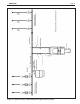
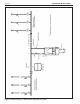
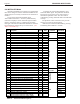
7.6 Domestic Hot Water Connection
For indirect water heater, connect aquastat for remote
sensor to terminals #7 & #8 or domestic hot water
sensor to terminals #9 & #10 (see Figure 24).
Domestic Hot Water Sensor PN is RE2337501
7.7 System Sensor
Connect the system sensor to connections labeled
"system sensor" on lead boiler only. #3 and #4
7.8 External Control Connections
If the unit is being controlled by an external 0-10VDC
signal, connect this to terminals 11 and 12. When
making the connections, follow the polarity designations
shown on the label. A "dry" alarm contact is located on
terminals 10 and 11 at high voltage panel.
Note: The 0-10VDC signal may be used to send a
modulation signal, or a temperature setpoint signal to
the boilers from a building management program (See
Section 9).
7.9 Analog Output (0 - 10 VDC)
Terminals 13 and 14 provide a 0 - 10VDC signal that
imitates the boiler outlet power. If the boiler is ring at
20%, the voltage will be 2.0 VDC If the boiler is ring
at 100%, the voltage will be 10.0 VDC.