
Installation / Operation Instruction Manual


Page 34
BRADFORD WHITE CORP
.
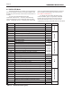
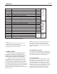
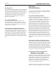
Table 15. Installer Parameters (part 1)
Laars SIT Parameters
Page 1
USER MODE
PARAMETER
Description DEFAULT
Parameter
U000
DHW set point 120 °F USHWDEM
U001
CH set point 130 ° F
US1SETP
U002
Installer Password 15
USPWD
U003
Display timeout 60 sec
DUI1
U004
Unit temperature (F / C) ° F DUI2
D00 = dhw Temp
INSTALLER MODE
PARAMETER
Description DEFAULT
Parameter
P01 Service notification months 12 SERVICET
P02
Service notification hours since last service 8760
SERVICERUN
P03
Service notification cycles 500
SERVICEOP
P04 Timeout for service mode 180 secs
* displayed as seconds
TMAXSERV
P06 Cascade address and configuration -1 CASCADD
P07 Cascade temperature set point 140 ° F CASCREGSETP
P08 Cascade temperature offset 10 °
F
CASCBLO
P09 Cascade temperature hysteresis from offset 20 °
F
CASCHYS
P11 min time a bic must remain on or off 30 sec
shows 300
CASCMINTONOF
P12
min next on time 60 sec
shows 600
CASCMINTNON
P23 Anti cycling time 30 sec
TANTICY
P24
Anti cycling dropoff temperature on s2 10 °F
ANTICYDROF
P25 0-10V to Power (fan speed) Enabled
FUNCFLAG
P26 0-10V to outlet setpoint Disabled
FUNCFLAG
P27 Alarm contact configuration Enabled
Enabled = NO / Disable
FUNCFLAG
P28 DHW demand blocks system pump Enable / Disable Disabled
FUNCFLAG
P29 System Pump Always On Enable / Disable Disabled
FUNCFLAG
P30
0-10V Input - Enable / Disable Enabled
FUNCFLAG
P31 BMS Voltage at Minimum 2 VDC
shows 200
V010AV
P32 BMS Voltage at Maximum 10 VDC
shows 1000
V010BV
P33 On threshold Voltage 1 VDC
shows 100
V010ON
P34 On hysteresis Voltage .5 VDC
shows 50
V010HYS
P35 BMS Rate at Minimum Voltage 20%
shows 200
V010APOW
P36 BMS Rate at Maximum Voltage 100%
shows 1000
V010BPOW
P37 BMS Temperature Setpoint at Minimum Voltage 70 °F
V010AC
P38
BMS Temperature Setpoint at Maximum Voltage 180 °F
V010BC
P39 Postcirculation time CH pump 30 sec
TPCIRCCH
P40 Postcirculation time DHW pump 30 sec
TPCIRCHW
P41 Postcirculation time System pump 30 sec
TPCIRCSYS
P42 Summer kick CH pump timer 20 sec
SKICKCH
P43 Summer kick DHW pump timer 20 sec
SKICKHW
P44 Summer kick System pump timer 20 sec
SKICKSYS
P45 Delta T Setpoint for CH pump speed control 20 °F
CHPMPSET
P46
Minimum output voltage for CH pump output 3.5 VDC
shows 350
CHPMPMINV
P47 Differential Max Fan Speed for DHW demand 0 RPM
MAXFANHWDIFF
P48 Differential Maximum Fan Speed for CH demand 0 RPM
MAXFANCHDIFF
ANTICYCLING & FLAGS
User settings
Service
Control
BMS
CIRCULATION PUMPS
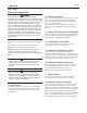
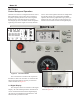
8.4 INSTALLER Mode
INSTALLER Mode is an extensive set of parameters
that can be changed to suit the individual installation and
should only be accessed by a trained service technician or
installer.
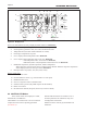
To access the INSTALLER Mode, hold
'Select/OK' and the down ˅ arrow key simultaneously
until U00 is displayed. Press 'Select/OK' again and then
release. Change the value to 15 and then press 'Select/OK'
again. The INSTALLER Mode Parameters will then
be accessible by pressing the Up or Down arrows.
(See Table 15 and Table 16)
To change the value of that parameter, press
Select/OK button again. The parameter will blink.
Pressing the Up or Down arrows will increase or
decrease the parameter value. The value will be
conrmed by pressing Select/OK button and the blink