
Installation / Operation Instruction Manual

Page 38
BRADFORD WHITE CORP
.
9.7.1 Cascade Manual Conguration
In some applications it may be necessary to congure the
cascade system manually. To do this, the boilers should
be wired as shown in the Auto Cascade section of the
manual. Then each individual control in the cascade
must have a specic address assigned by adjusting P06
“ Cascade address” on each boiler. To start, identify
the boiler that will be the “master” boiler. Navigate to
parameter P06 “cascade address” set to “0” and press
“Select” (do NOT press and hold select). Then press and
hold select.
Repeat this process for each boiler in the cascade setting
each address to a unique number.
The last step is to adjust all of the setpoints for the
installation application as shown in the Auto cascade
section of the manual.
9.7 Cascade Auto Conguration
To operate up to 8 boilers in cascade, the boilers
must be “daisy chained” together using Modbus
terminals A, B and GND, located on the boilers
terminal block. The wiring should be completed with at
least three wire shielded cable with ground. The ground
wire should be connected to a suitable chassis ground
on one end of the daisy chain only. Wire each boilers
terminal A in series with the next boilers terminal A
until all are connected. Repeat this process for Terminal
B and GND.
To congure the control system, identify which
boiler is going to be the “master” boiler for the cascade
system and navigate to installer parameter P06,
“Cascade Address”. Set the address to “0” and press
and hold “select”. When “auto cfg” appears on the
display press “select” to start the auto conguration
process. The auto conguration process will nd all
boilers connected to the “master” boiler and assign
addresses. When auto conguration is complete the
display should show “boilr #” where # is the total
number of boilers found in the cascade system.
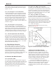
The nal steps are to set the individual setpoints
in the cascade system, which include P07 “Cascade
Setpoint”, P08 “Cascade off Hysteresis” and P09
“Cascade on hysteresis”. These variables must be set
to the appropriate values for the installation. When
setting P09 “cascade on hysteresis” the value should
NOT be less than P08 “Cascade off Hysteresis” as
P09 references the off point (P07+ P08) as the starting
point for the on hysteresis. An example of this is shown
below.
Correct settings:
P07 = 120°F
P08 = 10°F
P09 = 20°F
With these setting the modulation point is 120°F
The off point is 120°F + 10°F = 130°F
The on point is 130°F – 20°F = 110°F
Incorrect settings:
P07 = 120°F
P08 = 10°F
P09 = 5°F
With these setting the modulation point is 120°F
The off point is 120°F + 10°F = 130°F
The on point is 130°F – 5°F = 125°F
In this case the boiler is turning back on prior to
reaching the modulation point, which could lead to
short cycling.