
Installation / Operation Instruction Manual

Page 43
Brute LX
the fastening points on the right side of the control to
remove the hooks from the control panel. To replace
the control repeat the steps above in the reverse order
making sure to connect all wires in the proper location.
Place the appliance in operation following the steps
outlined in Section 10.
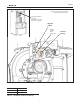
11.2.3 Ignitor Assembly
The ignitor assembly is a two rod system that consists
of a ground rod and a sense rod. To remove the ignitor
assembly, shut off the 120 Volt power supply to the
appliance. Turn off all manual gas valves connecting the
appliance to the main gas supply line. Remove the front
door of the boiler to gain access to the ignitor assembly.
Remove the two wires connected to the assembly. Then
remove the two bolts connecting the ignitor assembly
to the burner door. Remove and replace the old ignitor
assembly gasket. Reinstall a new ignitor assembly in
the reverse order if the old assembly is determined
defective. Replace gasket if necessary.
11.2.4 Flame Sensor
The ame sensor is a single rod system. To replace the
ame sensor electrode, shut off the 120 Volt power
supply to the boiler. Turn off all manual gas valves
connecting the boiler to the main gas supply line.
Remove the front door of the boiler to gain access to
the ame sensor electrode. Remove the ame sensor
wire from the electrode. Remove the two bolts fastening
the electrode to the boiler top. Remove and replace the
old ame sensor gasket. Reinstall a new ame sensor
electrode in the reverse order if the old electrode is
determined defective.
CAUTION
Igniters and sensors get hot and
can cause burns or injury.
11.2.5 Blower
The combustion air blower is a high-pressure centrifugal
blower with a variable speed motor. Speed of the motor
is determined by the control logic. 120 Volts remain on
to the blower at all times. If a blower change is required,
turn off the 120 Volt power and gas supply to the unit.
Take the front panel off. Disconnect the 120 Volt and
control signal connections from the blower. Disconnect
the bolts connecting the venturi to the blower housing.
Disconnect the fan outlet bolts from the burner door
blower arm. If the fan is determined to be defective
replace the existing fan with a new one reversing the
steps above. Make sure to install all of the required
O-rings and gaskets between the blower arm and the
blower and blower face and venturi ange.
11.2.6 Heat Exchanger Coils
Black carbon soot buildup on the internal surfaces of
the heat exchanger is caused by one or more of the
following; incomplete combustion, combustion air
problems, venting problems and heater short cycling.
Soot buildup or other debris on the heat exchanger may
restrict the ue passages.
If black carbon soot buildup on the heat exchanger is
suspected, disconnect electrical supply to the unit, and
turn off the gas supply by closing the manual gas valve
on the unit. Access the heat exchanger through the
burner at the top of the boiler, and inspect the tubing
using a ashlight and a mirror. If there is a buildup of
black carbon soot or other debris on the heat exchanger,
clean per the following:
CAUTION
Black carbon soot buildup on a dirty heat exchanger
can be ignited by a random spark or ame. To prevent
this from happening, dampen the soot deposits with
a wet brush or ne water spray before servicing the
heat exchanger.
1. Shut off the 120 Volt power supply to the boiler
2. Turn off all manual gas valves connecting the boiler
to the main gas supply line.
3. Disconnect all blower wiring and gas valve piping.
4. Remove the four bolts connecting the blower ange
to the burner ange.
5. Remove the burner assembly from the heat
exchanger.
6. Disconnect the condensate drain line.
7. Attach a longer hose to drain and run to a bucket.
8. Clean the heat exchanger by brushing light
accumulations of soot and debris. Use a brush
with soft bristle (non metal) to avoid damaging the
surface of the heat exchanger tubes or refractory.
CAUTION
Be careful not to damage refractory material located
at top and bottom of heat exchanger.
9. Once the tubes have been brushed clean rinse the
tubes and combustion chamber with a small amount
of water to rinse all of the debris out of the bottom
of the ue collector and into the longer condensate
trap line, which is being diverted into a separate
container.
NOTE: The Warranty does not cover damage caused
by lack of required maintenance, lack of water ow,
or improper operating practices.