
Installation / Operation Instruction Manual

The FT Series Heating Only, Boiler
Page 45
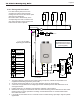
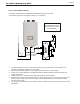
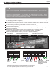
4.14.6 Indirect Water Heating
- Installer is responsible for all equipment and detailing required by local codes.
- The minimum pipe size of CH piping should be 1 ¼˝ in diameter.
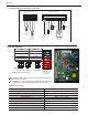
Auto Fill Valve
and Backow Preventer
Valves are NOT included
(Field Supplied).
Circulation pump
Check valve
Drain valve
Gate valve
Backflow preventer
Pressure Relief Valve
Expansion tank
Air separator
(Diaphragm-type)
Automatic air vent
Anti-scald rated
Mixing Valve
PRIMARY LOOP
CH
SUPPLY
CH RETURN
(SPACE HEATING)
ZONE 1
ZONE 2
ZONE 3
1" or 1-1/4"
min piping
depending
upon boiler
size.
Do not
exceed
12"
See
Note
SECONDARY LOOP
(SPACE HEATING)
Make-Up Water
DHW
Pump
Indirect DHW Tank
1. This piping diagram is meant to show system piping concept only. Installer is responsible for all
equipment and detailing required by local codes.
2. All closely spaced tees shall be 12” (or 4 pipe diameters) center to center spacing.
3. A minimum of 6 pipe diameters of straight pipe shall be installed upstream and downstream of all
closely spaced tees.
4. Install a minimum of 12 diameters of straight pipe upstream of all circulators.
5. Manufacturer strongly recommends the use of an anti-scald mixing valve at domestic hot water outlet
(boiler location) to reduce potential for scalding. Contact Manufacturer for recommended models.
Check with local codes.
6. It is strongly recommended to use a 10k Ohm sensor for DWH sensing, especially in high temp DHW
applications.
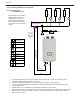
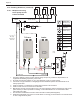
Circulation pump
Check valve
Drain valve
Gate valve
Backflow preventer
Pressure Relief Valve
Expansion tank
Air separator
(Diaphragm-type)
Automatic air vent
Anti-scald rated
Mixing Valve
PRIMARY LOOP
CH
SUPPLY
CH RETURN
ZONE 1
ZONE 2
ZONE 3
1”
Do not
exceed
12"
See
Note
SECONDARY LOOP
(SPACE HEATING)
Make-Up Water
DHW
Pump
Indirect DHW Tank