
Installation / Operation Instruction Manual

The FT Series Heating Only, Boiler
Page 49
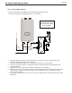
Electrical Connections
4.17 Electrical Wiring Connections
This appliance must be electrically grounded. Ensure the electrical receptacle that the boiler will be plugged
into, is properly grounded; if wiring directly.
Do not attach the ground wire to either the gas or the water piping as plastic pipe or dielectric unions may
isolate the Boiler electrically.
The wiring diagrams contained in this manual are for reference purposes only.
Refer to these diagrams and diagrams from external controls used with this appliance. Read, understand,
and follow all wiring instructions.
Do not disconnect the power supply when the unit is in normal operation. Damage caused by freezing is not
covered under the warranty.
Manual (Rocker) switch maximum allowable current for each circulator is 16 amps at 125VAC.
( Housing : Nylon #66 UL 94V-2 , Rocker : Nylon #66 UL 94V-2, Terminal : Copper Alloy )
Terminal block (External power connector) : DFT-20A-10P (20 amps at 300VAC)
DHW and CH pump terminals for external pump are live 120V limited to
2.0 A. They operate respective to an external call (e.g T-T) for heat.
WARNING
Install wiring and electrically ground boiler in accordance with authority having jurisdiction or, in the
absence of such requirements, follow the National Electrical Code, NFPA 70, and/or CSA C22.1
Electrical Code-Part 1 in Canada.
ELECTRICAL SHOCK HAZARD — For your safety, turn o electrical power supply at service
entrance panel before making any electrical connections to avoid possible electric shock hazard.
Failure to do so can cause severe personal injury or death.
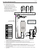
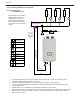
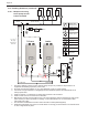
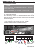
Manual Switch
External Power Connections
Low Voltage Connections
Thermostat
Connection or end
switch of multi-zone
relay panel
-continued on next page
CH
Pump
External
Input
DHW
Sensor
Cascade
Sensor
Low Water
Cut O
(jumpered)
Outdoor
Sensor
DHW
Pump
0 - 10V
CH PUMP
DHW PUMP
L N GL N G
T T
O / S
0-10V
INPUT
CASCADE
SYSTEM
SENSOR
DHW TEMP
SENSOR
L W C