
Installation / Operation Instruction Manual


The FT Series Heating Only, Boiler
Page 53
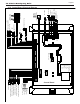
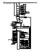
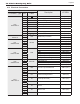
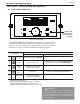
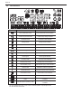
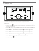
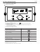
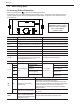
4.21 Electrical Connections
Connector
Description HT SELV
#, Location, Type PIN Label
CN9
65001WS-12
1 CASE GROUND HT (120V~)
2 L Power Supply Line HT (120V~)
3 CP1 Central Heating Pump HT (120V~)
4 IT Ignitor HT (120V~)
5 HEAT/CP2 CH Pump HT (120V~)
6 GV Gas Valve HT (120V~)
7
-
- -
8 N Power Supply Neutral HT (120V~)
9-12
N AC Power COM Line HT (120V~)
CN6
LW6A4-03
1
CP3 DHW Pump connection
HT (120V~)
3 HT (120V~)
CN1
SMW250-05D
1
RS-485
RS485 + SELV (5V)
2 RS485 - SELV (5V)
3 - -
4 RS485 + SELV (5V)
5 RS485 - SELV (5V)
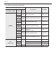
CN4
LWD1140-06D
1
FAN
Unuse -
2 GND SELV (30V)
3 VDD SELV (14V)
4 Fan power(start coil) SELV (30V)
5 Fan power(end coil) SELV (30V)
6 Fan speed feedback signal SELV (14V)
CN8
SMW250-04D
1
MCU ISP
GND SELV (5V)
2 ISP /Reset port SELV (5V)
3 ISP TOOL0 Data port SELV (5V)
4 VCC SELV (5V)
CN11
LWD 1140-16
1
HWL AC 24V Input Heat Demand SELV (12V~)
9
2
LWL Low Water Level Leakage Sensor SELV (12V~)
10
3
HD Central Heating Demand SELV (5V)
11
4
TH
Connect to the Display
Control(Thermostat)
SELV (14V)
12
5
APS Unuse -
13
6
EL Unuse -
14
7
BL Burner Limit SELV (14V)
15
8
HL Condensate Block SELV (14V)
16