Installation and Operation Instructions Document 1438 Installation and Operation Instructions for Brute MagnaTech ® Modulating Boiler Water Heater Model BMGH1600 Model BMGV1600 Model BMGH2000 Model BMGV2000 Model BMGH2500 Model BMGV2500 Model BMGH3000 Model BMGV3000 Model BMGH3500 Model BMGV3500 Model BMGH4000 Model BMGV4000 1,600 MBTU/h 1,999 MBTU/h 2,499 MBTU/h 3,000 MBTU/h 3,500 MBTU/h 4,000 MBTU/h 1,600 MBTU/h 1,999 MBTU/h 2,499 MBTU/h 3,000 MBTU/h 3,500 MBTU/h 4,000 MBTU/h FOR YOUR
Table of Contents SECTION 1 General Information 5.A.4 Suggested Boiler Piping Schematics 5.B Water Heaters..................................... 31 5.B.1 Water Quality....................................... 31 5.B.2 Heater Water Connections.................. 31 5.B.3 Cold Water Make-Up........................... 31 5.B.4 Freeze Protection................................ 32 5.B.5 Suggested Piping Schematics ........... 32 1.A Introduction........................................... 1 1.
SECTION 8 (continued) SECTION 9 Parameter Tables..................99 8.D.4 Cascade (Lead / Lag)........................ 69 8.D.4.a Cascade CH (Central Heat) ............... 74 8.D.4.a.1 Cascade CH Lead Settings............... 75 8.D.4.a.1.A Cascade Base / Drop Load............ 75 8.D.4.b Cascade DHW (Dom Hot Water)........ 76 8.D.4.c Cascade Rotation ............................... 77 8.D.4.c.1 Cascade Rotation Setup................... 77 8.D.4.d Cascade Redundancy......................... 78 8.D.
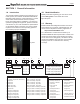
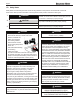
Page 1 SECTION 1 General Information 1.A Introduction 1.B Model Identification Primary information regarding your unit can be found on the Rating Plate on the outside face of the right-side panel. This manual includes information which will help you to install, operate, and maintain the Bradford White Brute MagnaTech high efficiency commercial boiler or volume water heater. Please read this manual completely before proceeding with the installation.
Page 2 1.D Safety Notes Safety Notes are used thoughout this manual to bring attention to the presence of hazards with various risk levels and to offer important information concering the life of this product. There are 3 basic types. 1 WARNING 2 CAUTION 3 Indicates an imminently hazardous situation which, if not avoided, can or will result in death or serious injury and can or will result in catastrophic property damage.
Page 3 WARNING Electrical Shock Hazard Electrical shock can cause severe injury, death or property damage. Disconnect the power supply before beginning installation or changing the wiring to prevent electrical shock or damage to the equipment. It may be necessary to turn off more than one power supply to disconnect. All electrical wiring is to be done in accordance with local codes, or in the absence of local codes, with: 1) The National Electrical Code ANSI/NFPA No. 70 - latest Edition, or 2) CSA STD.
Page 4 1.E Unit Overviews The next 3 pages give a visual reference to the basic component locations of the unit. Rating Plate Touchscreen On all models, the Control Panel hinges forward for easy access to wiring and to the heat exchanger. Doors open outward and are easily removed. Shown with front doors and left side panels removed.
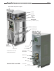
Page 5 Control Panel. See Figure 18 on page 37 Blower Manual Gas Valve Spark Generator Rating Plate. (on outside of panel) Heat Exchanger Condensing Unit Field Electrical Connections Gas Supply Power Pack Shown with front doors and left side panels removed.
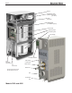
Page 6 Blower Manual Gas Valve (hidden behind main gas valve) Spark Generator Rating Plate. (on outside of panel) Control Panel Heat Exchanger Condensing Unit Gas Supply Air Intake and Filter Main Power Connections Field Electrical Connections Water Outlet Power Pack Water Inlet Shown with front doors and left side panels removed.
Page 7 1.
Page 8 1.G Dimensions Dimensions shown in inches (cm ) Model A 1600 29.3 (75 ) 2000 Model 2500 29.3 (75 ) A (78 ) 30.8 29.3 (75 ) 30.8 (78 ) 79.8 (203 ) B (221 ) 87.0 79.8 (203 ) 87.0 (221 ) 3500 34.5 (88 ) 97.0 (246 ) 4000 Model 34.5 (88 ) G 97.0 (246 ) H 1600 3000 2000 3500 2500 4000 3000 29.3 (75 ) 34.5 (88 ) 30.8 (78 ) 34.5 (88 ) 30.8 (78 ) B Dimensions shown C in inches (cm )D 79.8 (203 ) 38.0 (96 ) 57.5 (147 ) 79.8 (203 ) 97.0 (246 ) 87.0 (221 ) 97.0 (246 ) 87.0 (221 ) 1600 60.
Page 9 A H D C Air Inlet 2” Gas ALL Sizes Touchscreen Display K Pressure Relief Valve G Water Outlet B Water Inlet E N H H Air Inlet Gas K G F Water Outlet C ‘Knockdown’ Height D H Op�onal Flanges, Contact Factory ap on ALL Sizes E K REAR VIEW Models 3500 and 4000 differ from the other sizes in the location of J their Air Inlet and Gas Supply.
Page 10 1.H Unpacking 1.I This unit is shipped in a single crate. Carefully disassemble the crate and inspect the unit for any damage during shipping. Included in the crate and yet outside of the unit is the ‘Installation Kit’ box. Inspect the contents of the the Installation Kit box, making sure that all parts are included and not damaged. 1. Gromet, Nylon. 2. Box containing Outdoor Sensor 3. Box containing System Sensor 4. Tank Sensor 5. Spring Clip (used to hold tank sensor in sensor well) 6.
Page 11 1.J Clearances See Table 2 for Suggested Service Top Clearances earances Clearances d e m 1 1 0 0 Clearance Clearance to to Combustibles Combustibles inches cmcm inches Front Front 18 18 46 46 Back Back 11 11 28 28 LeftLeft 4 4 10 10 Right Right 4 4 10 10 TopTop 1 1 2.52.5 Table 1.
Page 12 SECTION 2 Venting and Combustion Air 2.A General Venting Information WARNING Selection of improper vent materials for installations that are installed in closets, or will be operated in high ambient temperature levels, may Lead to property damage, personal injury, or death. WARNING Failure to use the appropriate vent material, installation techniques, or glues and sealants could Lead to vent failure causing property damage, personal injury or death.
Page 13 insertion of a flue gas analyzer probe. The branch connection must be resealable with a cap or other means to ensure the vent system remains sealed. (See Figure 4) Consideration must be given to the placement and orientation of the flue gas sampling port to ensure that condensate is free to flow back into the unit and not collect anywhere in the vent system - including in the flue gas sampling port. General Ven�ng General Ven�ng This product requires a special ven�ng system.
Screen for horizontal PVC air pipe CA012004 CA012001 CA012001 CA012002 CA012003 CA012003 Screen for horizontal polypropylene air pipe CA012204 CA012201 CA012201 CA012202 CA012203 CA012203 Screen for vertical galvanized air pipe D2012204 D2012201 D2012201 D2012202 D2012203 D2012203 Screen for vertical PVC air pipe CA012404 CA012401 CA012401 CA012402 CA012403 CA012403 Screen for vertical polypropylene air pipe CA012604 CA012601 CA012601 CA012602 CA012603 CA012603 Page 14 In
Page 15 2.C.1 2.C.2 Category lV Vent Sizes Positive pressure vent systems may be either horizontally or vertically vented. The vent pipe used must be suitable for positive pressure, per the requirements shown in Section 2.B. Table 9 shows the pipe size and allowable maximum equivalent feet of piping allowed for both air and vent in a Category lV system. The forced draft combustion air blower in the unit has sufficient power to vent properly when the guidelines in Table 9 are followed.
Page 16 2.C.4 Common Vent Test NOTE: This section does not describe a method for common venting this unit. It describes what must be done when an unit is removed from a common vent system. This category IV unit requires special vent systems and fans for common vent. Contact the factory or your factory representative if you have questions about common venting this category IV unit.
Page 17 2.C.5 Combustion Air Boilers and water heaters must have provisions for combustion and ventilation air in accordance with the applicable requirements for Combustion Air Supply and Ventilation in the National Fuel Gas Code, ANSI Z223 1; or in Canada, the Natural Gas and Propane Installation Code, CSA B149.1. All applicable provisions of local building codes must also be adhered to.
Page 18 2.C.5.b Ducted Combustion Air The combustion air can be taken through the wall, or through the roof. The manufacturer offers accessories to use with ducted air systems, as shown in Table 8. See Table 7 to select the appropriate diameter air pipe. When taken from the roof, a field-supplied rain cap or an elbow arrangement must be used to prevent entry of rain water. (See Figure 7). Use ABS, PVC, CPVC, polypropylene, stainless steel, or galvanized pipe for the combustion air intake (See Table 7).
Page 19 *When vent terminal is less than 10 feet (3 m) horizontally from a forced air inlet, the terminal must be at least 3 feet (0.9 m) above the air inlet. (US only) U.S. Installations (see note 1) Canadian Installations (see note 2) A= Clearance above grade, veranda, porch, deck, or balcony 12 inches (30 cm) See note 6 12 inches (30 cm) See note 6 B= Clearance to window or door that may be opened Direct vent only: 12 inches (30 cm); Other than Direct vent: 4 ft (1.
Page 20 Multiple Vents 2” Min. (Typ) Window OUTLET Multiple Air Intakes 2” Min. (Typ) 84” 36” 90 12” 213 INLET 12” Figure 6. 2.D.2 Above expected snow line Terminals must be placed such that they are a Minimum of 12” above the expected snow line. Local codes may have more specific requirements and must be consulted. Refer to the NFPA 54 National Fuel Gas Code and your local codes for all required clearances for venting.
Page 21 (Place in section 3.5) Model 1600 Model 2000 Model 2500 Model 3000 Model 3500 Model 4000 Air intake screen for unit placed outdoors CA0011904 CA011901 CA011901 CA011902 CA0011903 CA0011903 Vent terminal for unit placed outdoors CA011804 CA011801 CA011801 CA011802 CA011803 CA011803 Table Table11. 3** Air - Air&&Vent VentAccessories Accessoriesfor forunits Unitsplaced Placedoutdoors Outdoors 2.
Page 22 SECTION 3 Gas supply and Piping 3.A Gas Supply and Piping All Installations must conform to the National Fuel Gas Code ANSI Z223.1/NFPA54, and/or local codes. In Canada, the installation must conform to the latest edition of CSA B149.1 Natural Gas and Propane Gas Installation Code, and/or local codes. Gas piping should be supported by suitable hangers or floor stands, not the unit. Natural Gas LP (propane) Min 4.0 IN - W.C. 8.0 IN - W.C. Max 10.5 IN - W.C. 14.0 IN - W.C. Table 12.
20 2,760 4,400 7,780 15,900 2 30 2,220 3,530 6,250 12,700 2 40 1,900 3,020 5,350 10,900 1 Page 23 50 1,680 2,680 4,740 9,660 1 60 1,520 2,430 4,290 8,760 1 3.B Gas Pipe Sizing 70 1,400 2,230 3,950 8,050 1 80 1,300 2,080 3,670 7,490 1 The following are gas line sizing examples from the National Fuel Gas Code. Size your gas lines properly, 3,450 90 1,220 1,950 7,030 1 based on your installation and all applicable codes.
Page 24 SECTION 4 Water Flow and Headloss Data SECTION 44 Water and Headloss DataData SECTION WaterFlow Flow and Headloss minimizing mineral buildup in the heater's 4.A. General Water Flow Information MagnaTherm units are water-tube type units that 4.A Water Flow Information 4.A.General General Water Flow Information require water flow for operation.
Page 25 Table 16. Minimum Boiler Water Flow Water Heater Water Flow and 4.C4.C.Water Heater Water Flow and Headloss Data Headloss Data Water flowflow and headloss for water heaters is based on Water and headloss for water heaters is based the on water’s hardness, to help minimize scale (mineral) the water's hardness, to help minimize scale buildup insidebuildup the heater’s tubes. Table (mineral) insidewater the heater's water17tubes.
Page 26 SECTION 5 Piping 5.A Boiler Water Piping 5.A.1 Boiler Water Connections NOTE: This unit must be installed in a closed pressure system with a minimum of 12 psi (82.7 kPa) static pressure at the boiler. The water piping should be supported by suitable hangers or floor stands. Do not support the piping with this unit. The hangers used should allow for expansion and contraction of pipe. Rigid hangers may transmit noise through the system resulting from the piping sliding in the hangers.
Page 27 5.A.4 • Hercules Chemical Company • Dow Chemical Company The boiler control offers some assistance with freeze protection, as long as the boiler is energized, and able to fire. 1. I f the outlet sensor detects less than 45°F, the control energizes the boiler pump. uggested Boiler Piping S Schematics This boiler is a high efficiency appliance.
Page 28 Note This drawing is a schematic representation of a piping style, and is not intended to be used as a working installation drawing. Local code requirements must be met. Low temp. radiant zone Low temp. radiant zone Air vent Water feed controls Expansion tank 4 pipe Dia. Max 4 pipe dia. max. Anti-scald mixing valve Indirect DHW tank Domestic hot water out Cold water Figure 9.
Page 29 Note This drawing is a schematic representation of a piping style, and is not intended to be used as a working installation drawing. Local code requirements must be met. Space heating zone circuits Low temp. radiant zone Space heating zone circuit Air vent Water feed controls 4 pipe dia. max. 4 pipe dia. max. Expansion tank 4 pipe dia. max. Common piping must be sized for the combined water flow of all of the boilers. Figure 10.
Page 30 Note This drawing is a schematic representation of a piping style, and is not intended to be used as a working installation drawing. Local code requirements must be met. Space heating zone circuits High temp. space heating zone circuit Space heating zone circuit Air vent Water feed controls 4 pipe dia. max. 4 pipe dia. max. Expansion tank 4 pipe dia. max. Common piping must be sized for the combined water flow of all the boilers. Anti-scald mixing valve 4 pipe Dia.
Page 31 5.B Water Heaters 5.B.1 Water Quality Water heaters must be installed in water conditions of 15 gpg hardness or less, with a pH range of 6.5 to 9.5 pH. Values outside of this range may reduce the life expectancy of the product. Operating at higher water hardness levels will cause heat exchanger fouling, erosion, or corrosion, Leading to premature component failure, reduced efficiency, heat exchanger failure or system failure. Failure of this type will not be warranted.
Page 32 5.B.4 Freeze Protection 5.B.5 If installing outdoors in a location that may experience freezing temperatures, precautions must be taken to prevent water in the heat exchanger and condensate inside and outside of the boiler from freezing. Damage due to freezing water or condensate is not covered by the warranty. Suggested Piping Schematics This heater is a high efficiency appliance.
Page 33 EXPANSION TANK Optional location for COLD WATER SUPPLY BUILDING RETURN Location of pump. Check valve Location of pump. EXPANSION TANK Check valve BALL VALVE (TYPICAL) NOTE: T his drawing shows suggested piping configuration and valving. Check with local codes and ordinances for additional requirements. NOTES: 1. Optional CWMU & recirculation line location. 2. Locate NTV DHW sensor or remote aquastat well in lower 1/3 of tank. 3. Back Flow Preventer may be required. Check local codes. 4.
Page 34 SECTION 6 Condensate Drain Trap This appliance creates condensation, as a by-product of high combustion efficiency. The condensate must be drained from unit and from the vent system. A combination condensate drain/trap is included the unit, for on-site assembly. See Figure 2 on page 10 This is used to drain the condensate from the heat exchanger of the unit. This condensate drain trap must be installed to prevent the accumulation of condensate.
Page 35 SECTION 7 Electrical Connections 7.A Installation Warnings CAUTION CAUTION The supply voltage to this unit must not be disconnected, except for service or isolation, or unless otherwise instructed by procedures outlined in this manual. To signal a call for heat, use the 24V field interlock, as shown in the wiring diagram. DO NOT MAKE AND BREAK THE LINE VOLTAGE TO THE UNIT TO SIGNAL A CALL FOR HEAT. A call for heat/end call for heat MUST be connected to the field interlock terminals.
Page 36 7.B Shown with outside panels removed for full servicing. Main Power Connections Field Electrical This unit is provided with an electrical Connections at the Terminal Block on the Control Panel. junction box in the rear panel for main See Figure 18 on page 37 power connections. See Figure 17. All power wires are factory installed between this junction box and the main high voltage box at the front of the Junction Box for Main Power unit.
Page 37 7.C Control Panel Layout Low Water Cutoff Auto Reset High Limit (optional) Manual Reset High Limit (optional) Boiler Controller (shown uncovered) Terminal Block Figure 18. Control Panel Components Lead Lag Figure 19. Field Connection Terminal Block 7.D Field Connections Wiring for all Field Connections must be run along the inside face of the available electrical raceway to the back of the unit. See Figure 17. and See Figure 19. output current of 1.5 amps.
Page 38 NOTE: When running the Power and Field Connection wirings between the units (Lead Lag, System Sensor, Outdoor Sensor, Building Automation, etc.), it is necessary to exit and enter the units through the lower back panels so that during future servicing, the wires are not in the way and do not have to be disconnected in order to remove the top and side panels.
Page 39 Figure 21. Jumper locations at the inputs 7.D.4 Heat Demands TT1 - if a thermostat/aquastat or end switch (isolated contact only) is used as a heat demand, connect to terminals 37 and 38 (See Figure 19 on page 37). TT1 functionality is configured on the touch screen on the CH1/DHW1 screens. TT2 – if an additional thermostat/aquastat or end switch (isolated contact only) is required as a heat demand, connect to terminals 39 and 40.
Page 40 7.D.7 RS 485 for Cascade (Lead Lag) Cascade - Prior to wiring units for cascade operations, select one unit as the Lead boiler/ heater. Other units connected to the Lead boiler/heater will be referred to as Lag units. Communication between Lead and Lag units is accomplished using RS485. When wiring these units for cascade operations, use terminals 57, 58, and 59 (See Figure 19 on page 37). Use 2-wire twisted pair, shielded w/drain (communication cable) between units.
Page 41 7.
Page 42 7.
Page 43 Modbus Address Type R/W 89 90 91 U16 U16 U16 Read Read Read 128 129 130 131 132 133 134 135 136 137 148 149 150 151 152 155 156 157 158 163 164 165 166 167 168 174 175 176 179 S16 S16 S16 S16 S16 S16 S16 S16 S16 S16 S16 S16 S16 S16 S16 S16 S16 S16 S16 S16 S16 S16 S16 S16 S16 S16 S16 S16 S16 Read/Write Read/Write Read/Write Read/Write Read/Write Read/Write Read/Write Read/Write Read/Write Read/Write Read/Write Read/Write Read/Write Read/Write Read/Write Read/Write Read/Write Read/Write Read/W
4 5 2 1 3 BK/O BK MAIN POWER SWITCH BL Y BK/O W G Figure 22. Wiring Diagram, model 1600 Page 1 of 2 RUN RELAY CONTACTS Analog Outputs Analog Inputs Heat Demands Sensor Inputs Dry Contacts Power Outputs 24N 13 L N L 18 19 20 PUMP 23 24 SYSTEM PUMP 31 32 SYSTEM RETURN + + + 47 48 49 50 51 52 0-10VDC BLOWER 0-10VDC (N/A on 1.6) C N.C. PUMP 46 43 BAS - 42 DHW + 41 DHW 45 40 TT - 2 44 39 TT - 2 BLOWER 0-10VDC (N/A on 1.
34 36 TT - 1 38 TT - 2 39 TT - 2 40 DHW 41 DHW 42 BAS 43 - 0-10VDC 44 + BLOWER 0-10VDC (N/A on 1.6) 45 - 46 + 47 - 48 + 49 - 50 + BLOWER 0-10VDC (N/A on 1.6) CASCADE RS485 N.C. 52 N.O. 53 4 51 54 N.C. 55 W C N.O.
4 5 2 1 3 6 BK/O BK MAIN POWER SWITCH 6-PIN CONNECTOR "E" BL Y BK/O W G Figure 23. Wiring Diagram, Models 2000 to 4000 L 23 24 SYSTEM PUMP 31 32 SYSTEM RETURN 52 N.C. C 51 RUN RELAY CONTACTS + 50 5 Ref. + 48 - 47 VFD 2.0 - 4.
RING DIAGRAM, SIT TROLS, MGT 2.0 - 4.0 O 39 TT - 2 Heat Demands - 0-10VDC 44 + 45 - 46 + 47 - 48 + 49 - 50 + 51 C 52 N.C. 53 N.O. 54 C 55 N.C. 56 N.O. 57 B 58 A 59 GND 60 B 61 A 62 GND Speed 2 Feedback 30 Main Gas Valve Spark Ignitor Pilot Gas Valve 43 VFD 2.0 - 4.
R O Y RED YELLOW BR BROWN ORANGE BK G BK W BLACK V GY VIOLET GRAY YELLOW G WHITE Y BL W GRAY O ORANGE BLUE GY R VIOLET RED GREEN V BR BLUE BL G BK W N BK R 6 5 4 3 2 1 LV BK R PE N LV BK T1 A1 HV A2 HV 1 2 3 4 5 6 W T2 W TRANSFORMER PH1500PP W T2 BK T1 A2 A1 CONTACTOR TRANSFORMER PH1500PP 6 5 4 3 2 1 BK L2 W CONTACTOR W L1 BK L1 BK L2 BK PE 1 2 3 4 5 6 W BK BK BK H N H N N BR BR H BK BR H BK BK 2 AMP D D B A C MATER
GND L2 L1 G R BK G G BK BR R BLACK BROWN RED WIRE COLOR LEGEND Figure 25.
Figure 26. High Voltage Wiring Diagram Model 1600, 220V / 240V Single Phase G R BK W GRAY WHITE FMA56A V GY VIOLET G BL BLUE Y YELLOW BK L1 BK R R L2 X1 X3 X2 X4 H2 H3 H1 R A2 T2 SP1000MGMJ LV BK T1 A1 W H4 HV BK R L2 CONTACTOR L1 BK BK 10 AMP BK BK BK L1 L2 2 AMP L1 L2 L1 L2 H H N N G G - W + BK FINISH NA NA BK/O 1 2 3 H 120V BK G W + BK Y - APPR ENGR DRAFT AL 1/19/15 JAT 1/19/15 APPROVALS DO NOT SCALE DRAWING.
V BL G Y O R BR BK OLOR LEGEND GND NEUT 120VAC G G W BK R PE BK 1 U/T1 R L1 6 5 4 3 2 1 4 BK LV L2 2 W 0-10V L1 R BK VFD V/T2 L2 N 5 BK XF2 G BL TRANSFORMER PH1500PP W/T3 L3 BLOWER HV 1 2 3 4 5 6 BK L2 W W BK BK BK T1 A1 W W T2 A2 CONTACTOR L1 BK BK R W 6 5 4 3 2 1 LV BK H BR N BR HV 2 AMP H BK XF1 30AMP BREAKER TRANSFORMER PH1500PP BK 10 AMP LINE 3 LOAD 4 1 2 3 4 5 6 N W BK G G R 240V 2 BLK B A C D FINISH MATER
Figure 28.
4 G BL V BLUE VIOLET Y YELLOW GREEN R O RED ORANGE BK BR BROWN WIRE COLOR LEGEND Figure 29.
BK R 208 VOLT GY/BL 120 X3 X2 X4 H2 H3 H1 X1 L1 L2 L3 17 PE W BK TRANSFORMER VOLT SP1000SP G L1 L2 L3 GY/R H4 FIELD CONNECTIONS BLOCK FLUE INTAKE SWITCHES TB1-44B W 16 0-10V W/T3 L3 G G TB28B W L2 L1 T2 T1 CONTACTOR L3 A1 T3 A2 1 3 BK A C B HIGH VOLTAGE BR O SP1000ACP X3 X2 H2 H3 X4 X1 H1 X4 X1 W BK 120 TRANSFORMER VOLT H4 480 VOLT BK G VFD PE W BK TB2 6C CONT A2 10 AMP TB2 W - + BK P V H1 H2 H3 G 3 6 W G W 2 5 1 4 BK
Page 55 7.
Page 56 7.
Page 57 Dual Element X1-1 208/480/600VAC (3PH/60Hz) L1 L2 L3 R2 VFD L1 U L2 V L3 W 5 2 30 16 M1 BLOWER MOTOR TB1-52 TB1-57 TB1-51 TB1-58 OFF 4.
Page 58 SECTION 8 Control Operation 8.A The Home Screen 8.A.1 Name Security Home Screen Active Icons Icon Description Displays the current lock status icon. Touch the lock icon to lock or unlock the Touchscreen Display. See Section 8.B on page 60 Quick Start Provides quick access to the most commonly used parameters for easy installation. Configure Provices access to ALL of your configurations for a detailed setup of the unit. See See Section 8.C on page 61 Section 8.
Page 59 8.A.2 Keypad Operations NOTE: You can always tell exactly where you have navigated to by looking at the icons in the Navigation Bar. In this example you are in Home / Configure / Central Heat / Central Heat One Shows the current setting of the Parameter. These windows will reflect the allowable ranges of the parameter To delete the current setting before entering in the new value. “Up and Down” arrows are used to increment the setting accordingly.
Page 60 8.B Login to Lock / Unlock the Display Screen Password Protection: To change configuration or parameters, a password is required. The control system includes three levels of password protection. Touch the 'Current Lock Status' icon at the top of the screen. 1- U SER password is lhs. This password is for ‘Safe’ access ‘Non-Critical’ adjustments and functions. Use this password if you want to make adjustments without fear of altering the critical configuration of the system.
Q U I C K S TA R T 8.C Quick Start Quick Start will allow a user to configure the BASIC functionality of the control, without going through all of the parameters that are available. The 6 BASIC functionalites are • Central Heat, • Domestic Hot Water, • Outdoor Reset, • Warm Weather Shutdown, • Anti-short Cycle ` and • Time & Date 8.C.1 CH (Central Heat) ”CH” stands for “Central Heat.” It is used for space heating demands.
Page 62 8.C.1.a CH1 (Central Heat, One) Q U I C K S TA R T 1 • Enable/Disable – This allows CH1 to be enabled/disabled. The default setting is Enabled. • Set Point – This is the set point temperature. 8.C.1.b CH2 (Central Heat, Two) 2 To navigate to the CH2 Quick Start Screen, touch the CH2 Icon on the CH Quick Start Selection Screen. The CH2 screen will be have the same look and functionality as the CH1 Screen. 8.C.2 DHW (Domestic Hot Water) ”DHW” stands for “domestic hot water.
Q U I C K S TA R T Page 63 8.C.3 Outdoor Reset Outdoor reset adjusts a boiler’s setpoint based on outdoor air temperature. This is for boilers only, and is not used for domestic water. To navigate to the Outdoor Quick Start Screen, touch the Outdoor Icon on the Quick Start Screen. The Outdoor Quick Start Screen allows the adjustment of the following parameters: • Enable/Disable – Enables and disables the outdoor reset functionality.
Q U I C K S TA R T Page 64 8.C.5 Anti-Short Cycle To navigate to the Anti-Short Cycle Quick Start Screen, touch the Anti-Short Cycle Icon on the Quick Start Screen. The Anti-Short Cycle Quick Start Screen allows adjustment of the following parameter: • C ycle Time – The amount of time after a heat demand is satisfied that the unit will wait to satisfy the next active heat demand. NOTE: Anti-Short Cycle Time does not apply to DHW heat demands. 8.C.
C O N F I G U R AT I O N 8.D Configuration This area of the controller allows access to all parameters available, based on the access level that is unlocked. To navigate to the Configuration Screen, touch the Configure Icon in the lower left portion of the Home Screen. The Configuration Screen shows all configurable parameters.
C O N F I G U R AT I O N Page 66 8.D.1 CH (Central Heat) “CH” stands for “Central Heat.” It is used for space heating demands. On the Configure Screen, touch the CH thermometer icon to navigate to the CH Selection Screen There are two identical heat demands, CH1 and CH2, each with independent control algorithms and independent inputs on the input terminal strip, see 7.D on page 37 From the CH Selection Screen, touching CH1 navigates to the CH1 8.D.1.
C O N F I G U R AT I O N PID 8.D.1.a.1 Page 67 PID Parameters Note that in most cases, PID parameters will not need to be changed. The PID Parameters Screen allows adjustment to the following parameters: • O n Hysteresis – The temperature below the set point (Set Point – On Hysteresis) at which the control begins calculating the PID output to turn on stages.
C O N F I G U R AT I O N Page 68 8.D.3 Outdoor Reset Outdoor reset adjusts a boiler’s setpoint based on outdoor air temperature. This is for boilers only, and is not used for domestic water. The Outdoor Parameters Screen allows the adjustment of the following parameters: • Enable/Disable – Enables and disables the outdoor reset functionality. • M aximum Outdoor Temperature – The outdoor temperature at which the unit will use the minimum water temperature as the set point.
C O N F I G U R AT I O N Page 69 8.D.4 Cascade (Lead / Lag) An installation with two or more units may be configured for cascade operation (Lead / Lag). Up to eight units can be cascaded and controlled together. To navigate to the Cascade Screen, touch the Cascade Icon on the Configuration Screen. The Cascade Screen provides four navigation icons to configure the system for cascade operations.
Page 70 About Cascading (Lead / Lag) -continued Log In Parameter User Settings Installer OEM Min Max Default Unit Base Load X X 40 100 65 % Drop Load X X 20 100 20 % Min On Time X X 30 600 60 Seconds Min Off Time X X 30 600 30 Seconds Table 21. Parameter Settings is limited to 20% minimum (instead of the allowable minimum firing rate of 5%).
Page 71 As the load increases: As the load decreases: • Until all units are firing, no unit is requested to exceed the base load value. • As long as all units are firing – the base load value can be exceeded, as long as all units maintain the same firing rate. • Additional units are added once the Base Load Value has been reached and the Min On Time timer has expired.
Page 72 About Cascading (Lead / Lag) -continued Low demand: The first boiler in sequence ignites and gradually increases firing rate to satify the heat demand.
eight boilers reach the Base Load Value , all units are allowed to increase firing rate (same at all boilers) up to maximum firing rate. Decreasing demand: As the demand decreases, once the requested firing rate reaches the Drop Load Value , the eighth boiler turns off. Continued decreasing demand: As the demand decreases, once the requested firing rate reaches the Drop Load Value , the seventh boiler turns off. This pattern continues as demand continues to decrease until there is a single boiler firing.
C O N F I G U R AT I O N Page 74 8.D.4.a Cascade CH To navigate to the Cascade CH Configuration Screen, touch the Cascade Icon on the Configuration Screen, then touch the Cascade CH Icon on the Cascade Configuration Screen. The Cascade CH Configuration Screen allows adjustment of the following parameters: • A ddress – When manually addressing each boiler/heater for cascade operations, this parameter is used to set the local boiler/heater address. Each boiler/heater must have a unique address.
C O N F I G U R AT I O N Page 75 8.D.4.a.1 Cascade CH Lead Settings To navigate to the Cascade CH Lead Configuration Screen, touch the Cascade Icon on the Configuration Screen, then touch the Cascade CH Icon on the Cascade Configuration Screen, and then touch the Lead Settings Icon on the Lead unit. The Cascade CH Lead Configuration Screen allows adjustment of the following parameters: • Set Point – This is the temperature the cascade heat demand is trying to satisfy.
Page 76 8.D.4.a.1.A Base / Drop Load • Base Load – Is the firing rate that must be achieved prior to adding another unit to satisfy the heat demand. • Drop Load – A s the demand for heat decreases, this is the firing rate that units turn off. The last unit to fire is the first to get turned off. • Min On Time – As the demand for heat increases, this is the delay time prior to firing additional units.
C O N F I G U R AT I O N Page 77 8.D.4.c Rotation To navigate to the Cascade Rotation Screen, touch the Cascade Icon on the Configure Screen, then touch the Rotation Icon on the Cascade Configuration Screen. The Cascade Rotation Screen is a view only screen. This screen indicates how many units are connected in a cascade configuration, the order in which each unit will run, and the percent at which each unit is running.
C O N F I G U R AT I O N Page 78 8.D.4.d Redundancy To navigate to the Cascade Redundancy Screen, touch the Cascade Icon on the Configuration Screen, then touch the Redundancy Icon on the Cascade Configuration Screen. The Cascade Redundancy Screen allows the selection of one of three options for redundancy in cascade systems.
C O N F I G U R AT I O N Page 79 8.D.6 Pumps The Pump Configuration Screen allows adjustment of the following 7 parameters: • Boiler Pump Control – This parameter provides the ability to set the boiler pump functionality to be: Auto – the pump will turn on automatically upon a call for heat. Always On – the pump will run continuously. Off Dur ing DHW – the pump will not turn on during a DHW heat demand.
Page 80 C O N F I G U R AT I O N 8.D.6.a Variable Speed Pump Control Variable speed pump control and the Vari-Prime Screen allows the adjustment of the following parameters: • O n Delay – Upon a call for heat, once the unit ignites, this is the amount of time the unit will wait prior to modulating the pump speed. • P roportional Gain – This value is the corrective action that is proportional to the error (Set Point – Control Temperature).
C O N F I G U R AT I O N Page 81 8.D.7 Manual Firing Rate To navigate to the Manual Firing Rate Screen, touch the Manual Firing Rate Icon on the Configuration Screen. The Manual Firing Rate Control Screen allows the adjustment of the following parameters: • E nable/Disable – Enables and disables the manual firing rate functionality. • F an Speed – With the manual firing rate functionality enabled, an operator can manually set the firing rate.
Page 82 C O N F I G U R AT I O N 8.D.8.a Delta T Parameters To navigate to the Delta T Parameters Screen, touch the Temp Limits Icon on the Configuration Screen, then touch the Delta T Parameters button on the Temperature Limits Parameters Screen. The Delta T Parameters Screen allows adjustment of the following parameters: • E nable/Disable – Enables/disables the Delta T temperature functionality.
C O N F I G U R AT I O N Page 83 8.D.9 External The External Configuration Screen applies to the 0-10VDC (4-20mA) analog input BAS signal, and allows adjustment of the following parameters: To navigate to the External Configuration Screen, touch the External Icon on the Configuration Screen. • C ontrol Mode – This parameter provides the ability to either disable external control or configure the unit for Boiler Set Point or Firing Rate control mode.
Page 84 C O N F I G U R AT I O N 8.D.9.a External – Remote Set Point External (0 – 10VDC or 4 – 20mA) • A n External heat demand can be initiated by a Building Automation System (BAS) using a 0-10VDC or 4-20mA signal. This input can be configured for Remote Set Point or Remote Firing Rate operations. • W ith Remote Set Point selected, the unit will initiate a heat demand once the analog input signal exceeds the Demand On value.
C O N F I G U R AT I O N Page 85 8.D.9.b External Firing Rate With External Firing Rate selected, the unit will initiate a heat demand once the analog input signal exceeds the Demand On value. Once the demand is initiated, the analog input signal must be lower than Demand Off to remove the heat demand. The external analog signal will activate stages as shown in Figure 42.
C O N F I G U R AT I O N Page 86 8.D.11 Miscellaneous Features To navigate to the Miscellaneous Features Screen, touch the Miscellaneous Features Icon on the Configuration Screen. The Miscellaneous Features screen provides navigation for the following items: • P riorities – To set the Demand Priorities for all configured CHW or DHW heating demands. The higher the number, the higher the priority it is assigned. • A nti-Short Cycle – To navigate to the Anti-Short Cycle Configuration Screen.
C O N F I G U R AT I O N Page 87 8.D.11.a Demands Priorities To navigate to the Demands Priorities Screen, first go to the Miscellaneous folder. At the Demands Priorities screen select each configured demand and assign a priority number. The higher the number, the higher the priority that demand is assigned. Remember to always save the new setting with the button. 8.D.11.
Page 88 C O N F I G U R AT I O N 8.D.11.c Warm Weather To navigate to the Warm Weather Configuration Screen, touch the Miscellaneous Features on the Configuration Screen, then touch the Warm Weather Icon on the Miscellaneous Features screen. The Warm Weather Configuration Screen allows adjustment of the following parameters: • T emp Min – Upon an active warm weather shutdown condition, this is the temperature at which the unit will reset the shutdown condition to satisfy a heat demand.
C O N F I G U R AT I O N Page 89 8.D.11.d COM Port, BMS The control has Modbus and BACnet MSTP (RS485) protocols on board, for use with Building Management Systems. Gateways can be used for other communication protocols. To navigate to the COM Port Configuration Screen, touch the Misc Icon on the Configuration Screen, then touch the COM Port Icon on the Misc Configuration Screen.
Page 90 C O N F I G U R AT I O N 8.D.11.e Temperature Conversion To navigate to the Temperature Conversion Configuration Screen, touch the Temperature Conversion Icon on the Miscellaneous Features screen. The Temperature Conversion Configuration Screen allows adjustment of the following parameter: • Conversion unit – This parameter can be set to Fahrenheit or Celsius. 8.D.11.
C O N F I G U R AT I O N 8.D.12 Page 91 Login To navigate to the Login Screen, touch the Lock Icon on ANY screen. The Login Screen allows the operator to make parameter adjustments based on the level of the login credentials. See Section 8.B on page 60 Table 23 on page 99 and Table 24 on page 102 indicate which parameters are available with each login level.
Page 92 8.E SERVICE Service Screens To navigate to the Service Screen, touch the Service Icon in the lower left portion of the Home Screen. Available only to the factory or technician qualified at the OEM level. 8.E.1 Burner Navigate to the Burner Screen by touching the Burner Button on the Service Screen.
SERVICE Page 93 8.E.2 Digital I/O ( Input / Output ) There are two screen associated with the Digital I/O: Digital I/O Screen-Inputs; Digital I/O Screen-Outputs. Navigate to the Digital I/O Screen by touching the Digital I/O Button on the Service Screen. Digital I/O Inputs: The indicator light associated with the input is green when the input is satisfied. For example, if there is adequate flow, the flow switch is satisfied, and the flow switch digital input indicator light is green.
SERVICE Page 94 8.E.3 Analog I/O Navigate to the Analog I/O Screen by touching the Analog I/O Button on the Service Screen. There are two screens associated with the Analog I/O: Analog I/O Inputs; Analog I/O Outputs. Analog I/O Input: There are three types of analog inputs; temperature sensors, flame signal, and voltage/current (VDC/ mA). Wiring of these inputs are covered in SECTION 7 NOTE: If the input is not attached, the value will be zero.
SERVICE Page 95 8.E.4 Screen Settings Timeout Navigate to Screen Settings by touching the Screen Button on the Service Screen. There are two adjustable screen settings: Light Timeout and AutoLock Timeout. • L ight Timeout allows the user to adjust the amount of time the touch screen backlight will remain lit after user interaction has ceased. • A utoLock Timeout allows the user to adjust the amount of time the touch screen will remain unlocked with no user interaction. 8.E.
SERVICE Page 96 8.E.6 Restart Touchscreen & Recalibrate Touching the Restart Button on the Service Screen reboots the display. If the touchscreen seems to be out of alignment, it can be recalibrated by pressing the Restart Button, promptly touching (and holding) the touch screen. Follow the calibration procedure as shown on the touch screen. 8.E.7 Factory Reset Touching the Factory Reset Button on the Service Screen resets all touch screen adjustable parameters back to the factory default setting. 8.E.
Page 97 8.F Messages and USB 8.F.1 Messages The ‘Messages’ icon at the bottom of the home screen displays an ‘Exclamation Point’ when messages are present. Press the icon to see the message(s). 8.F.2 USB Functionality The USB port is on the back of the display. To access it, open both panels and look for the black USB cable extending from the back of the display. See Figure 44. When the USB icon has appeared over the Message icon, press the USB icon to access the USB menu.
Page 98 8.G Active Demands The Active Demand Window indicates the status of active heat demands. Sec�on 6.5 Ac�ve Demands A black heat demand icon indicates the heat demand that is currently being satisfied. A “greyed out” heat demand icon is either in priority than the heat demand that is currently being satisfied, or the heat demand has reached Ac�ve lower Demand Bar Demand Bar indicates the status of ac�ve heat demands. A black heat demand icon set point, The butAc�ve remains active.
Page 99 SECTION 9 Parameter Tables (MGH and MGV) Time & Date Hour Minute Month Day Year CH1 CH1 Enable/Disable CH1 Setpoint CH1 Priority CH1 On Hysteresis CH1 Off Hysteresis CH1 Proportional Gain CH1 Integral Time CH1 Derivative Time Max Power CH2 CH2 Enable/Disable CH2 Setpoint CH2 Priority CH2 On Hysteresis CH2 Off Hysteresis CH2 Proportional Gain CH2 Integral Time CH2 Derivative Time Max Power DHW DHW Enable/Disable DHW Setpoint DHW Priority DHW On Hysteresis DHW Off Hysteresis DHW Proportional Gain DH
le r al In st U se Boilers r Page 100 Minimum Maximum Default Unit Cascade CH On Hysteresis Cascade CH Off Hysteresis Cascade CH Maximum Lag Temperature Base Load Drop Load Min On Time Min Off Time Cascade Redundancy x x x x x x x 0F 0F 40 F 40% 20% 30 secs 30 secs 20 F 20 F 210 F 100% 100% 600 secs 600 secs 10 F 10 F 180 F 65% 20% 60 secs 30 secs °F/C °F/C °F/C % % Seconds Seconds Loss of Lead Setup x Disable Boiler Internal Setpoint/ Redundant Lead Disable N/A Hybrid Hybrid Enable/Dis
le r al In st U se Boilers r Page 101 Minimum Maximum Default Unit 5 210 F 210 F 100% 100% 100% 100% 25% 25% 0-10 VDC/ 4-20 mA 5 180 F 110 F 100% 20% 100% 20% 15% 10% 0-10 VDC N/A °F/C °F/C % % % % % % VDC/mA Pump Only N/A 40 F 5F °F/C °F/C External Control Priority Maximum Setpoint Minimum Setpoint Maximum Firing Rate Minimum Firing Rate Demand Max Demand Min Demand On Demand Off Input Type Anti- Frost x x x x x x x x x x 1 40 F 40 F 20% 20% 0% 0% 0% 0% N/A Anti Frost Mode x Disable A
Page 102 In st al le r U Heater se r Table 24.
al le r In st U Heater se r Page 103 Minimum Maximum Default Units Min On Time Min Off Time Cascade Redundancy x x 30 secs 30 secs 600 secs 600 secs 60 secs 30 secs Seconds Seconds Loss of Lead Setup x Disable Boiler Internal Setpoint/ Redundant Lead Disable N/A Hybrid Hybrid Enable/Disable Hybrid Lag Mode Hybrid Setpoint Hybrid Differential Hybrid Delay Pump Configuration x x x x x Disable Disable 80 F 5F 0 min Enable Enable 180 F 20 F 720 min Disable Disable 130 F 10 F 30 min N/A
Page 104 Minimum Anti Frost Mode x Disable Anti- Frost Setpoint Anti- Frost Hysteresis Anti- Frost (continued) x x 32 F 2F Pump Only/ Pump & Burner 120 F 10 F Anti- Frost Pump Control x NA Boiler/ DHW/ System Boiler N/A 240 secs 60 secs Seconds Fahrenheit Fahrenheit °F/C Modbus / BACnet 76800 255 NA NA 4194303 300 secs BACnet 76800 127 NA NA 600000 300 secs N/A Bits/Second N/A N/A N/A N/A Seconds Enable Enable N/A 3600 secs 3600 secs 600 secs 600 secs Seconds Seconds Enable Di
Page 105 SECTION 10 Initial startup Instructions 10.A Filling the Boiler System 1. Ensure the system is fully connected. Close all bleeding devices and open the make-up water valve. Allow the system to fill slowly. 2. If a make-up water pump is employed, adjust the pressure switch on pumping system to provide a minimum of 12 psi (81.8 kPa) at the highest point in the heating loop. 3.
Page 106 10.B Initial Operation The initial setup must be checked before the unit is put into operation. Problems such as failure to start, rough ignition, strong exhaust odors, etc. can be due to improper setup. Damage to the boiler resulting from improper setup is not covered by the limited warranty. 10.B.1 WARNING If any odor of gas is detected, or if the gas burner does not appear to be functioning in a normal manner, close the main gas shutoff valve. Do not shut off the power switch.
Page 107 10.B.2 Combustion Setup Procedure This section describes how to make adjustments to the main gas valve for proper combustion at both high and low fire conditions. Required tools: Screwdrivers, Torx bits, Allen Wrench Set, Combustion Analyzer Gas Valve Shown is a model 3000. All units have a similar design with the gas valve similarly located. High fire adjustment Low fire adjustment Figure 45. High and Low Fire Adjustments on the Gas Valve 1.
Page 108 4. Also at the Firing Rate screen, set the Fan Speed to Maximum as shown in the image below. 5. Provide a call for heat to the TT-1 terminals (terminal 37 and 38) and allow the system to transition to run mode. 6. Once in run mode and firing at 100%, see image below, using a combustion analyzer, adjust the high fire adjustment screw on the main gas valve to obtain the correct CO2 measurement shown in Table 23. If the CO2 measurement is high, consult the factory for assistance. 7.
Page 109 9. Allow the unit the stabilize at the minimum firing rate, see image below. Using a combustion analyzer, observe the CO2 readings and adjust the low fire adjustment screw on the main gas valve to obtain the correct low fire CO2 measurement shown in Table 23. Consult the factory if the CO2 reading is above the specified value in the table. 10. Remove the heat demand applied at the TT-1 terminals. 11. Navigate to the Firing Rate screen and disable the burner.
Page 110 Model 1,600 2,000 2,500 3,000 3,500 4,000 Gas Type High Fire CO2 Low Fire CO2 Pressure Differential Natural 9.0% ± 0.2 .25 lower than high fire CO2 0.5” to 1.2” wc* Propane 10.0% ± 0.2 .25 lower than high fire CO2 0.5” to 1.2” wc* Natural 9.0% ± 0.2 .25 lower than high fire CO2 0.5” to 1.2” wc* Propane 10.0% ± 0.2 .25 lower than high fire CO2 0.5” to 1.2” wc* Natural 9.0% ± 0.2 .25 lower than high fire CO2 0.9” to .09” wc Propane 10.0% ± 0.2 .
Page 111 10.E.2 Pre-purge Closed In Pre-purge Closed mode, the boiler/heater blower will turn on and run at Pre-Purge Speed. The boiler/heater verifies that the APS transitions from open to closed. The gas valve and spark are off. The duration of this mode is defined by the Pre-Purge APS Closed Time. If the APS closes and the Pre-Purge APS Closed Time expires, the boiler/heater will transition to Transition to Pre-Ignition mode.
Page 112 Timer Value Description Pre-Purge APS Max Open Time 5 seconds The max time the boiler/heater will wait for the APS to close. Pre-Purge APS Closed Time 30 seconds The APS has to be closed for this amount of time prior to mode transition. Pre-Ignition Time 10 seconds With the blower at Ignition Speed, the spark will be on for this amount of time prior to mode transition.
Page 113 SECTION 11 Maintenance 11.A System Maintenance Do the following once a year: 1. Lubricate all the pumps in the system, per the instructions on the pump. 2. Inspect the venting system for obstruction or leakage. Periodically clean the screens in the vent terminal and combustion air terminal (when used). 3. Remove and inspect the air filter. Clean with soapy water if needed. Be sure that filter is dry before reinserting back into air filter box. Replace air filter if damaged. 4.
Page 114 After the valve has been removed, reassemble in reverse order making sure to include all gaskets and O-rings. Turn on the manual gas valves and check for gas leaks. Turn on the main power. Place the unit in operation following the instructions in SECTION 10. Once the boiler is operating, check for leaks again and confirm all fasteners are tight. 11.B.
Page 115 11.B.8 Heat Exchanger Tubes Black carbon soot build-up on the external surfaces of the heat exchanger is caused by one or more of the following: incomplete combustion, combustion air problems, venting problems or heater short-cycling. Soot buildup or other debris on the heat exchanger may restrict the flue passages. If black carbon soot buildup on the heat exchanger is suspected, disconnect the electrical supply to the unit and turn off the gas supply by closing the manual gas valve on the unit.
Page 116 SECTION 12 Troubleshooting Condition Flow Switch Low Water Cut Off Information • Insufficient flow at the outlet of the boiler/heater • Auto-reset Condition • Annunciation – “Warning Flow switch open” on Message Screen • Insufficient water level in the boiler/heater heat exchanger. • Manual-reset Condition • Annunciation – on Navigation Bar Corrective Action • Faulty boiler/heater pump – replace pump. • Faulty pump contactor – replace contactor.
Page 117 SECTION 12 Troubleshooting (continued) Condition Flow Switch Outlet Sensor Drift Low Water Cut Off Information • Insufficient flow at thereadings outlet of do thenot Dual element sensor boiler/heater agree. • Auto-reset Condition Manual-reset Condition • Annunciation – “Warning FlowBar switch open” on Navigation on Message Screen Lockout:water Outlet • Insufficient levelProbe in the Drift boiler/heater heat exchanger.
Page 118 SECTION 13 Replacement Parts Use only genuine Manufacturer’s replacement parts. 13.A General Information 8 ATION CONTAINED HEREIN ARE YSTEMS CO. AND SHALL NOT BE HER DOCUMENTS, USED OR ACTURING OR ANY OTHER AUTHORIZED IN WRITING To order or purchase parts, contact your nearest manufacturers dealer 5or 6 7 distributor. (See the back cover of this manual for the manufacturers website). 4 3 13.
Page 119 View from Back 14 17 18 19 7 16 6 13.B.1Final Final Assembly, Part Numbers 13.B.2 Assembly, Part Numbers Item # 1 1-A 1-B 2 3 4 4 4 4 5 6 7 8 9 10 11 12 13 14 15 16 17 18 19 1600 2000 Description Part No. Part No.
Page 120 16 11 23 2 21 24 6 D E 9 25 10 26 20 15 3 7 12 4 A 15 18 13 14 3 25 26 17 22 AC DISTRIBUTION BOX SHOWN FOR REF ONLY DETAIL E 10 1 19 24 8 3 5 9 DETAIL A DETAIL D Frame and Jacket Assembly
Page 121 13.B.1 Frame and Jacket Assembly, Part Numbers Item # Description 1 Base assembly 2 Filter Filter assembly (incl.
Page 122 1 3 2 4 13.B.4 Control Panel, Part Numbers Item # 1 2 3 4 Description Manual reset high limit (opt.) Auto reset high limit (opt.) Low water cutoff Control board & Standoffs 13.B.3 1600 Part No. E2217800 RE2217700 RE2075100 30N7101 Control Panel, Part Numbers 2000 Part No. E2217800 RE2217700 RE2075100 30N7101 2500 Part No. E2217800 RE2217700 RE2075100 30N7101 3000 Part No. E2217800 RE2217700 RE2075100 30N7101 3500 Part No. E2217800 RE2217700 RE2075100 30N7101 4000 Part No.
Page 123 5 16 9 17 8 4 6 DETAIL 7 11 13 A 2 15 14 12 10 13.B.5 Air / Gas System, Part Numbers (Model 1600) Item # 1 2 3 4 5 6 7 8 9 10 11 12 13 14 15 16 17 13.B.
Page 124 17 5 9 16 8 4 6 DETAIL 11 3 7 15 13 14 2 12 10 2 13.B.
Page 125 12 4 8 14 13 SEE DETAIL A FOR PILOT TUBE PLACEMENT 5 7 9 DETAIL A DETAIL 6 11 3 10 2 13.B.7 Air / Gas System, Part Numbers (Models 2500 & 3000) Item # 1 2 3 4 5 6 7 8 9 10 11 12 12 13 14 13.B.
Page 126 10 8 6 7 9 11 12 5 17 13 11 14 3 4 15 3 PART16 NUMBER DESCRIPTION 40N5068 STANDARD 40N5070 CSD-1 2 1 13.B.8 Air / Gas System, Part Numbers (Models 3500 & 4000) Item # 1 2 3 4 5 6 7 8 9 10 10 11 12 13 14 15 16 17 3500 4000 1 1 S2125300 GASKET, AF-12 BLOWER INTAKE, MAGNATHERM Description Part No. Part 1 1 S2124800 ORING, 6" INo. D X 3/32, #163, EPDM Burner L2019900 1 1 S2124600 GAL2019900 SKET, BURNER TOP, MGT 4.
Page 127 4 5 6 12 1 10 9 7 3 11 13 8 2 13.B.9 AC Distribution Box, Part Numbers (Model 1600) 1600 120V 208V 220/240V AC DISTRIBUTION BOX ASSEMBLY PART NUMBERS (MODEL1600) 1PH 1PH 1PH Item # Description Part No. Part No. Part No.
Page 128 13.B.10 AC Distribution Box, Part Numbers (Model 2000) Item # 1 2 3 4 5 6 7 8 9 10 11 12 13 14 - Description VFD with program Bushing, nylon Transformer GFCI receptacle Circuit breaker, 2A Circuit breaker, 10A Circuit breaker, 3A Relay, 115V, DPST Transformer 120/24V Panel, AC distribution box Cover, box, power input Box, power input Support, power input box Circuit Breaker Wire harness assembly, circuit breakers to transformer (not shown) 13.B.9 120V 1PH Part No.
Page 129 13.B.
Page 130 6 2 6 2 5 5 3 1 4 3 1 4 ITEM NO. 1 2 ITEM NO.
Page 131 Waterway Outlet Assembly, Part Numbers 2 1 6 8 3 7 5 4 9 13.B.14 Waterway Outlet Assembly, Part Numbers 1600 2000 Part Number 2500by Boiler Size 3000 3500 4000 Item # Description Item # Description Part No. Part Part No. 3000Part No. 3500 Part No. Part No. 1600 2000No.
Page 132 3 8 17 6 33 2 16 34 18 1 6 17 15 23 12 19 13 30 21 26 23 39 22 32 9 31 14 26 9 39 3 4 25 36 37 7 29 20 28 27 26 39 24 38 10 11 40 35 Gas Train Assembly (Models 1600, 2000, 2500 and 3000) 5
Page 133 13.B.
Page 134 3 4 5 6 7 16 8 29 18 15 30 23 25 27 26 28 32 31 24 22 14 13 16 2 12 17 14 14 34 7 11 36 14 13 12 17 19 1 20 21 9 31 10 32 33 35 Gas Train Assembly (Models 3500 and 4000) 1 70-236 1 W2000300 2 S2123500 PIPE PLUG, MA 2 P2089600 ADAPTER, FEMALE 1 P2089300 ADAPTER, 1/4 TUBE 1 40N6040 GAS TRA 1 40N6031 GAS TRAIN 1 IO Manual/QTY. V2022300 VALVE, MANUA WASHER, SEAL VALVE, PART NO.
Page 135 13.B.
Notes: Color The AHRI Certified™ mark is designed to be reprod contained. Artwork is provided for your use in vario Select the appropriate file for use based on the app please contact AHRI’s Certification Program Admin Generic Marketing Application Product Labels PMS 300, C=100, M=42, Y=0, K=0, R=0, G=101, B=189, HTML: #0065BD or Black. PMS 300, C=100, M HTML: #0065BD, or HLW 200 Lafayette St.