
Installation / Operation Instruction Manual


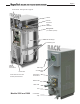
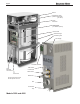
Table Of Contents
- Brute MagnaTech
- Table of Contents. Page 1
- SECTION 1 General Information
- SECTION 2 Venting and Combustion Air
- SECTION 3 Gas supply and Piping
- SECTION 4 Water Flow and Headloss Data
- SECTION 5 Piping
- SECTION 6 Condensate Drain Trap
- SECTION 7 Electrical Connections
- SECTION 8 Control Operation
- 8.A The Home Screen
- 8.B Login to Lock / Unlock the Display Screen
- 8.C Quick Start
- 8.D Configuration
- 8.E Service Screens
- 8.F Messages and USB
- 8.G Active Demands
- SECTION 9 Parameter Tables
- SECTION 10 Initial startup Instructions
- SECTION 11 Maintenance
- SECTION 12 Troubleshooting
- SECTION 13 Replacement Parts
- 13.A General Information
- 13.B Component Illustrations, Parts Lists, and Part Numbers
- 13.B.1 Final Assembly, Part Numbers
- 13.B.2 Frame and Jacket Assembly, Part Numbers
- 13.B.3 Control Panel, Part Numbers
- 13.B.4 Air / Gas System, Part Numbers (Model 1600)
- 13.B.5 Air / Gas System, Part Numbers (Model 2000)
- 13.B.6 Air / Gas System, Part Numbers (Models 2500 & 3000)
- 13.B.7 Air / Gas System, Part Numbers(Models 3500 and 4000)
- 13.B.8 AC Distribution Box, Part Numbers (Model 1600)
- 13.B.9 AC Distribution Box, Part Numbers (Model 2000)
- 13.B.10 AC Distribution Box, Part Numbers (Models 2500 to 4000)
- 13.B.11 Inlet Waterway Assemblies, Part Numbers
- 13.B.12 Outlet Waterway Assemblies, Part Numbers
- 13.B.13 Gas Train Assembly, Part Numbers(Models 1600, 2000, 2500 and 3000)
- 13.B.14 Gas Train Assembly, Part Numbers (Models 3500 and 4000)

i
SECTION 1 General Information
1.A Introduction........................................... 1
1.B Model Identication ............................. 1
1.C Warranty ............................................... 1
1.D Safety Notes ......................................... 2
1.E Unit Overviews ..................................... 4
1.F Gas Train Components ........................ 7
1.G Dimensions........................................... 8
1.H Unpacking .......................................... 10
1.I Locating the unit ................................. 10
1.J Clearances ......................................... 11
SECTION 2 Venting and Combustion Air
2.A General Venting Information............... 12
2.B Vent and Air Pipe Material .................. 12
2.B.1 Venting Reqs Unique to Canada ........ 12
2.B.1.a Flue Gas Sampling Port - ................... 12
2.B.1.b Exhaust Vent Terminal - ..................... 13
2.C Vent and Air Pipe Sizing ..................... 14
2.C.1 Category lV Vent Sizes....................... 15
2.C.2 Category II Vent Sizes ........................ 15
2.C.3 Common Venting ................................ 15
2.C.4 Common Vent Test ............................. 16
2.C.5 Combustion Air ................................... 17
2.C.5.a Combustion Air From Room ............... 17
2.C.5.b Ducted Combustion Air....................... 18
2.D Locating Vent and Comb Air Terminals 18
2.D.1 Side-wall Vent Terminal ...................... 18
2.D.2 Side-wall Combustion Air Terminal ..... 20
2.D.3 Vertical Vent Terminal ......................... 20
2.D.4 Vertical Combustion Air Terminal ........ 20
2.E Outdoor Installation ............................ 21
2.F Installations in the
Commonwealth of Massachusetts ..... 21
SECTION 3 Gas supply and Piping
3.A Gas Supply and Piping ....................... 22
3.B Gas Pipe Sizing .................................. 23
SECTION 4 Water Flow and Headloss Data
4.A General Water Flow Information ........ 24
4.B Boiler Water Flow & Headloss Data ... 24
4.C Water Heater Water Flow
and Headloss Data ............................. 25
SECTION 5 Piping
5.A Boiler Water Piping ............................. 26
5.A.1 Boiler Water Connections ................... 26
5.A.2 Cold Water Make-Up .......................... 26
5.A.3 Freeze Protection ............................... 26
5.A.4 Suggested Boiler Piping Schematics
5.B Water Heaters .................................... 31
5.B.1 Water Quality ...................................... 31
5.B.2 Heater Water Connections ................. 31
5.B.3 Cold Water Make-Up .......................... 31
5.B.4 Freeze Protection ............................... 32
5.B.5 Suggested Piping Schematics ........... 32
SECTION 6 Condensate Drain Trap .......34
SECTION 7 Electrical Connections
7.A Installation Warnings .......................... 35
7.B Main Power Connections ................... 36
7.C Control Panel Layout .......................... 37
7.D Field Connections............................... 37
7.D.1 Power ................................................. 37
7.D.2 Dry Contacts ....................................... 37
7.D.3 Temperature Sensors ......................... 38
7.D.4 Heat Demands ................................... 39
7.D.5 Analog In and Analog Out .................. 39
7.D.6 Dry Contacts. Run & Alarm ................ 39
7.D.7 RS 485, for Cascade (Lead / Lag)...... 40
7.D.8 RS485 BMS........................................ 40
7.E Modbus and BACnet Memory Map .... 41
7.F Wiring Diagrams ................................. 44
7.G High Voltage Wiring Diagrams ........... 48
7.H Ladder Diagrams ................................ 55
SECTION 8 Control Operation
8.A The Home Screen ............................. 58
8.A.1 Home Screen Active Icons ................. 58
8.A.2 Keypad Operations............................. 59
8.B Login to Lock / Unlock ..................... 60
8.C Quick Start ........................................ 61
8.C.1 Quick Start CH (Central Heat) ............ 61
8.C.2.a Quick Start CH1 (Central Heat, One) . 62
8.C.2.b Quick Start CH2 (Central Heat, Two) . 62
8.C.2 Quick Start DHW (Domestic Hot Water) 62
8.C.3 Quick Start Outdoor Reset ................ 63
8.C.4 Quick Start Warm Weather Shut Down 63
8.C.5 Quick Start Anti-Short Cycle .............. 64
8.C.6 Time & Date ...................................... 64
8.D Conguration .................................... 65
8.D.1 CH (Central Heat) ............................... 66
8.D.1.a CH1 (Central Heat, One) .................... 66
8.D.1.a.1 PID Parameters ................................ 67
8.D.1.b CH2. (Central Heat, Two) ................... 67
8.D.2 DHW (Domestic Hot Water) ............... 67
8.D.3 Outdoor Reset ................................... 68
Table of Contents