
Installation / Operation Instruction Manual
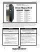
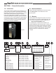


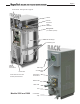
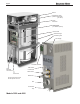
Table Of Contents
- Brute MagnaTech
- Table of Contents. Page 1
- SECTION 1 General Information
- SECTION 2 Venting and Combustion Air
- SECTION 3 Gas supply and Piping
- SECTION 4 Water Flow and Headloss Data
- SECTION 5 Piping
- SECTION 6 Condensate Drain Trap
- SECTION 7 Electrical Connections
- SECTION 8 Control Operation
- 8.A The Home Screen
- 8.B Login to Lock / Unlock the Display Screen
- 8.C Quick Start
- 8.D Configuration
- 8.E Service Screens
- 8.F Messages and USB
- 8.G Active Demands
- SECTION 9 Parameter Tables
- SECTION 10 Initial startup Instructions
- SECTION 11 Maintenance
- SECTION 12 Troubleshooting
- SECTION 13 Replacement Parts
- 13.A General Information
- 13.B Component Illustrations, Parts Lists, and Part Numbers
- 13.B.1 Final Assembly, Part Numbers
- 13.B.2 Frame and Jacket Assembly, Part Numbers
- 13.B.3 Control Panel, Part Numbers
- 13.B.4 Air / Gas System, Part Numbers (Model 1600)
- 13.B.5 Air / Gas System, Part Numbers (Model 2000)
- 13.B.6 Air / Gas System, Part Numbers (Models 2500 & 3000)
- 13.B.7 Air / Gas System, Part Numbers(Models 3500 and 4000)
- 13.B.8 AC Distribution Box, Part Numbers (Model 1600)
- 13.B.9 AC Distribution Box, Part Numbers (Model 2000)
- 13.B.10 AC Distribution Box, Part Numbers (Models 2500 to 4000)
- 13.B.11 Inlet Waterway Assemblies, Part Numbers
- 13.B.12 Outlet Waterway Assemblies, Part Numbers
- 13.B.13 Gas Train Assembly, Part Numbers(Models 1600, 2000, 2500 and 3000)
- 13.B.14 Gas Train Assembly, Part Numbers (Models 3500 and 4000)

Page 5
Blower
Models 2500 and 3000
Air Intake and
Filter
Water Outlet
Main Power
Connections
Water Inlet
Vent
Power Pack
Field
Electrical
Connections
Condensate
Trap
Heat Exchanger
Condensing Unit
Gas Supply
Manual
Gas Valve
Rating Plate.
(on outside of panel)
Spark
Generator
Control Panel. See Figure 18 on page 37
Shown with front doors and
left side panels removed.