Installation and Operation Instructions Document 1244C Installation and Operation Instructions for Hydronic Boiler Model BMT2H Water Heater Model BMT2V Sizes 200, 300, 400 FOR YOUR SAFETY: This product must be installed and serviced by a professional service technician, qualified in hot water boiler installation and maintenance. Improper installation and/or operation could create carbon monoxide gas in flue gases which could cause serious injury, property damage, or death.
Page 2 Bradford White Corp TABLE OF CONTENTS SECTION 1 General Information................3 1.A 1.B 1.C 1.D 1.E 1.F 1.G 1.H Introduction................................................. 3 Model Identification..................................... 4 Warranty..................................................... 4 Dimensions................................................. 4 Locating the Appliance............................... 4 Locating Pump-Mounted Water Heater with Respect to Storage Tank(s)...........
Brute Deluxe (200, 300, 400), Install & Operating SECTION 1 General Information USING THIS MANUAL – Because the Brute Deluxe Boilers and Brute Deluxe Water Heaters are identical appliances, with the exception of materials of manufacture, labels and ultimate use application, this manual provides information for the proper installation, operation and maintenance of both products.
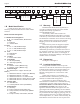
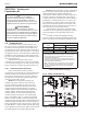
Page 4 1 Bradford White Corp 2 3 4 B M T 2 B M SERIES T 5 6 7 9 10 11 12 13 14 15 16 C USAGE 2 8 FUEL LOCATION H 0 2 SIZE 0 0 N C V 0 3 0 0 P 0 4 0 0 FIRING MODE C REVISION 2 3 K HEAT EXCHANGER OPTIONS CODE B X X C L N N P PUMP OPTIONS S G 2 5 1.B Model Identification Consult the rating plate on the unit. The following information describes the model number structure.
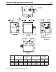
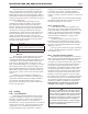
Brute Deluxe (200, 300, 400), Install & Operating Page 5 Dimensions shown in inches, cm. Model 200 300 400 A in. 20.5 26.5 33.6 cm 52 67 85 Combustion Air Connection B* in. cm 4 10 4 10 6 15 Vent Connection C* in. 5 6 7 cm 13 15 18 *Air and vent connections may be on top or back of the Brute Deluxe, and are field convertible. Figure 1. Dimensional Data - Non Pump Mounted. Horizontal (Cat III) Vent Pipe Size in.
Page 6 Bradford White Corp Dimensions shown in inches, cm. Model 200 300 400 A in. 20.5 26.5 33.6 cm 52 67 85 Combustion Air Connection B* in. cm 4 10 4 10 6 15 Vent Connection C* in. 5 6 7 cm 13 15 18 *Air and vent connections may be on top or back of the Brute Deluxe, and are field convertible. Figure 2. Dimensional Data - Pump Mounted. Horizontal (Cat III) Vent Pipe Size in.
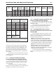
Brute Deluxe (200, 300, 400), Install & Operating Page 7 Vent Collar Size Horizontal Vent Pipe Diameter Intake Air Collar & Pipe Diameter Max. Pipe Length in cm in cm in cm ft m 200 5 13 4 10 4 10 50 300 6 15 5 13 4 10 400 7 18 6 15 6 15 Heater Size Table 1. Required Clearance From Combustible Material Recommended Service Access Clearance inches cm inches cm Left Side 1 2.5 24 61 Right Side 1 2.5 24 61 Top 1 2.5 12 30 Back 1 2.
Page 8 SECTION 2 Venting and Combustion Air WARNING For indoor installations, as an additional measure of safety, National Combustion Co. strongly recommends installation of suitable Carbon Monoxide detectors in the vicinity of this appliance and in any adjacent occupied spaces. AVERTISSEMENT Pour des installations intérieures, National Combustion Co.
Brute Deluxe (200, 300, 400), Install & Operating The combustion air can be taken through the wall, or through the roof. When taken from the wall, it must be taken from out-of-doors by means of the Bradford White horizontal wall terminal (see Table 1). When taken from the roof, a field-supplied rain cap or an elbow arrangement must be used to prevent entry of rain water (see Figure 3). Use single-wall galvanized pipe for the combustion air intake (see Table 1 for appropriate size).
Page 10 AVERTISSEMENT Le fonctionnement d’appareils connectés à un évent commun bouché peut provoquer de sérieuses blessures corporelles ou la mort. Des dispositifs de sécurité doivent être mis en place pour empêcher que les appareils soient utilisés avec un évent commun bouché.
Brute Deluxe (200, 300, 400), Install & Operating Page 11 U.S. Installations (see note 1) Canadian Installations (see note 2) A= Clearance above grade, veranda, porch, 12 inches (30 cm) 12 inches (30 cm) deck, or balcony B= Clearance to window or door that may Direct Vent Only: 12 inches (30 cm) be opened Other Than Direct Vent: 4 feet (1.
Page 12 6. If the boiler or water heater uses ducted combustion air from an intake terminal located on the same wall, locate the vent terminal at least 3 feet (0.9m) horizontally from the combustion air terminal, and locate the vent terminal at least 1 foot (0.3m) above the combustion air terminal WARNING The outdoor vent terminal gets hot. Unit must be installed in such a way as to reduce the risk of burns from contact with the vent terminal.
Brute Deluxe (200, 300, 400), Install & Operating 1. Detailed instructions for the installation of the venting system design or the venting system components; and 2. A complete parts list for the venting system design or venting system. (d) MANUFACTURER REQUIREMENTS – GAS EQUIPMENT VENTING SYSTEM NOT PROVIDED.
Page 14 7. system properly vents when tested as outlined above, return doors, windows, exhaust fans, fireplace dampers and any other gas burning appliance to their previous conditions of use. Any improper operation of the common venting system should be corrected so that the installation conforms with the National Fuel Gas Code, ANSI Z223.1/NFPA 54 and/or CSA B149.1, Natural Gas and Propane Installation Codes.
Brute Deluxe (200, 300, 400), Install & Operating SECTION 3 3.A Page 15 Gas Supply and Piping Gas Supply and Piping pressures in excess of 0.5 psig (3.45 kpa). The unit must be isolated from the gas supply system by closing its individual manual shutoff valve during any pressure testing of the gas supply piping system at test pressures equal to or less than 0.5 psig (3.45 kpa). 10. The appliance and its gas connection must be leak tested before placing it in operation. 11. Purge all air from gas lines.
Page 16 SECTION 4 4.A Bradford White Corp Water Connections — Brute Deluxe Boiler 4.A.1 Heating System Piping: Hot Supply Connections — Boiler NOTE: This appliance must be installed in a closed pressure system with a minimum of 12 psig (82.7 kPa) static pressure at the boiler. Hot water piping should be supported by suitable hangers or floor stands. Do not support piping with this appliance. Due to expansion and contraction of copper pipe, consideration should be given to the type of hangers used.
Brute Deluxe (200, 300, 400), Install & Operating Page 17 4.B Water Connections — Brute Deluxe Water Heater 35°F 4.B.1 Water System Piping — Water Heater Hot water piping should be supported by suitable hangers or floor stands. Do not support piping with this appliance. Due to expansion and contraction of copper pipe, consideration should be given to the type of hangers used. Rigid hangers may transmit noise through the system resulting from the piping sliding in the hangers.
Page 18 Figure 6. Hydronic Piping — Multiple Boilers, Low Temperature System. Figure 7. Hydronic Piping — One Boiler, Multi-Temperature System.
Brute Deluxe (200, 300, 400), Install & Operating Figure 8. Hydronic Piping — Primary-Secondary, Reverse-Return. Figure 9. Hydronic Piping — Primary-Secondary, Reverse-Return, Low Temperature.
Page 20 The minimum inlet water temperature for the Brute Deluxe is 130°F (54°C) to avoid condensing on the copper coils. 4.B.2 Hot Water Supply Piping —Water Heater Follow the tank manufacturer’s guidelines for completion of the hot water system connections. NOTE: A listed temperature and pressure relief valve listed as complying with the Standard for Relief Valves and Automatic Gas Shutoff Devices for Hot Water Supply Systems (ANSI Z21.22/CSA 4.
Brute Deluxe (200, 300, 400), Install & Operating Model (Size) 200 gpm ft Temp Rise °F Page 21 lpm m Temp. Rise °C S N H S N H S N H S N H S N H S N H 23 35 45 1.9 4.4 7.3 15 10 8 87 132 170 0.6 1.3 2.2 8 6 4 300 23 35 45 2.0 4.5 7.4 22 15 11 87 132 170 0.6 1.4 2.3 12 8 6 400 23 35 45 2.0 4.5 7.4 30 19 15 87 132 170 0.6 1.4 2.3 17 11 8 Notes: 1. S = soft water (1 to 7.5 grains hardness) 2. N = normal water (7.
Page 22 Bradford White Corp KEY: WATER CATEGORY GRAIN HARDNESS PER GALLON 1 THROUGH 7.5 S = SOFT N = NORMAL 7.6 THROUGH 17 OVER 17 H = HARD PPM / 17.1 = Grains Per Gallon 1 SU CAUTION: THIS DRAWING SHOWS SUGGESTED PIPING CONFIGURATION AND VALVING, CHECK WITH LOCAL CODES AND ORDINANCES FOR ADDITIONAL REQUIREMENTS. PP LY 2 NOTES: 1. OPTIONAL CWMU & RECIRC. LINE LOCATION. 2. LOCATE DHW SENSOR OR REMOTE AQUASTAT WELL IN LOWER 1/3 OF TANK. 3 4 CW MU 3. BACK FLOW PREVENTER MAY BE REQUIRED.
Brute Deluxe (200, 300, 400), Install & Operating Page 23 CAUTION: THIS DRAWING SHOWS SUGGESTED PIPING CONFIGURATION AND VALVING, CHECK WITH LOCAL CODES AND ORDINANCES FOR ADDITIONAL REQUIREMENTS. KEY: WATER CATEGORY GRAIN HARDNESS PER GALLON 1 THROUGH 7.5 S = SOFT N = NORMAL 7.6 THROUGH 17 OVER 17 H = HARD PPM / 17.1 = Grains Per Gallon 3 4 MU CW 1 . RC CI RE 2 LY PP SU 2 NOTES: 1. OPTIONAL CWMU & RECIRC. LINE LOCATION. 2. LOCATE DHW SENSOR OR REMOTE AQUASTAT WELL IN LOWER 1/3 OF TANK. 3.
Page 24 SECTION 5 Bradford White Corp Electrical Connections Single pole switches, including those of safety controls and protective devices must not be wired in a grounded line. NOTE: All internal electrical components have been pre-wired. No attempt should be made to connect electrical wires to any other location except the wiring box. 5.A Main Power Connect a 15 amp. fused, 120-volt supply to the main power switch. Both hot and neutral wires are provided for connections inside the boiler jacket.
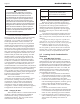
Brute Deluxe (200, 300, 400), Install & Operating Logic Diagrams. L1 120 VAC MAIN PWR SW 120 VAC 120 VAC IGN CTL HSI IGNITOR BK L1 W IGN CTL IGN CTL IGN CTL IGN CTL L1 IGN/120 IGN/FS L2 IGN CTL F1 F2 BK 4 24 VAC IGN CTL 24V GND FIELD INTERLOCK IGN CTL 24V GND FUSIBLE LINK MODEL 200 ONLY RELAY 4 CTL BD 3 7 6 GAS VALVE FIE FIE -2 -2 BL/R BK T BK F1 F2 PDR 6 4 TB1 24 FC +VAC 8 BLACK BROWN RED ORANGE YELLOW GREEN BLUE VIOLET GRAY SLATE WHITE WIRE COLOR Figure 14.
TAGE 2 TAGE 1 TL H A R +24 WIRE COLOR BLACK BROWN RED ORANGE YELLOW GREEN BLUE VIOLET GRAY SLATE WHITE DESIGNATION BK BR R O Y G BL V GY S W BK IGN IGN 240 120 BK F1 F2 G Y W 24V IGN/FS L1 L2 IGNITOR W W BK BK R STAGE 1 GAS VALVE C G BR/BK NO FLOW SWITCH PRESSURE SWITCH AIR BOX/BURNER R FIELD INTERLOCK BL/R BL/R TH PSW VAL GND E0253400 FUSE F1 TRANSFORMER 115 VAC INPUT 24 VAC OUTPUT BL/R BK 115V 24 FC +VAC BL/R BK MP UIPPED) Figure 16. Wiring Diagram, Boiler.
+24 BK BR R O Y G BL V GY S W DESIGNATION WIRE COLOR F1 BK F2 IGN IGN 240 120 BK BLACK BROWN RED ORANGE YELLOW GREEN BLUE VIOLET GRAY SLATE WHITE M E23802 TB1 4 AGE 2 AGE 1 TL A R MP IPPED) Figure 17. Wiring Diagram, Volume Water Heater.
Page 28 SECTION 6 6.A 1. 2. 3. 4. 5. 6. 7. 8. 9. 10. 11. 12. 13. 14. 15. Bradford White Corp Operating Instructions Filling the Boiler System Ensure the system is fully connected. Close all bleeding devices and open make-up water valve. Allow system to fill slowly. If make-up water pump is employed, adjust pressure switch on pumping system to provide a minimum of 12 psi (81.8 kPa) at the highest point in the heating loop.
Brute Deluxe (200, 300, 400), Install & Operating LEDs State Description 1. Power 2. Heat – On = call for heat; Flashes for Boiler sensor error 3. DHW – On = call for DHW; Flashes for outdoor sensor error 4. WWSD – On = Outdoor Reset AND WWSD Active AND control in WWSD; Flashes for outdoor sensor error, operation continues with fixed boiler target of 140°F. When a call for HEAT and/or DHW is present the pump contact (5A max) will be energized.
Page 30 Bradford White Corp Boiler Minimum target is set to Boiler Minimum + differential/2. 2. Target Max - The boiler target maximum is the point at which the stages will start to turn off to maintain a maximum water temperature. The Boiler Maximum water temperature is set by setting dip switch #4: Boiler Maximum 210°F (Off) / 190°F (On).
Brute Deluxe (200, 300, 400), Install & Operating Page 31 detected, the gas valve will close and the ignition module will attempt ignition again (up to two more times, for a total of three attempts.) If all three attempts fail, the ignition control will lock out. If flame is sensed, the burner will continue to fire as long as there is a call for heat, and none of the safety circuit is interrupted. If there is a call for stage 2 on a 2-stage unit, that valve will be energized.
Page 32 with water and all air has been bled from both. Open all valves. 3. Observe all warnings on the Operating Instructions label and turn on gas and electrical power to appliance. 4. Switch on the appliance power switch located on the right side of the unit. 5. The Brute Deluxe will enter the start sequence, as long as the unit is being called for heat.
Brute Deluxe (200, 300, 400), Install & Operating 6.G Shutting Down the Brute Deluxe 1. 2. 3. Switch off the main electrical disconnect switch. Close all manual gas valves. If freezing is anticipated, drain the Brute Deluxe and be sure to also protect building piping from freezing. This step to be performed by a qualified service person. 6.H To Restart the Brute Deluxe If drained, follow Section 6.1 in this manual for proper filling and purging. 1. 2. 3. 4. 5. 6. 7. 8.
Page 34 The gas and electric controls on the appliance are engineered for long life and dependable operation, but the safety of the equipment depends on their proper functioning. It is strongly recommended that a qualified service technician inspect the basic items listed below every year. a. Ignition control b. Ignitor c. Water temperature control d. Automatic gas valve e. Pressure switches and tubing f. Blower g. High limit h. Pump (if required) i. Relays j. Flow switch k. Gas train l.
Brute Deluxe (200, 300, 400), Install & Operating 7.B.7 Transformer The Brute Deluxe’s transformer is not capable of supplying control voltage for external devices such as zone valves, which must have their own separate power supply. Should a transformer need replacing, shut off the 120-volt power. Unplug the transformer wires, remove the mounting screws and remove the transformer. Replace transformer in the reverse order. 7.B.
Page 36 SECTION 8 8.A Bradford White Corp Trouble Shooting Resolving Lockouts There are many causes of lockouts. The three most common causes are: (1) inadequate gas supply, (2) poor combustion, (3) ignitor failure. 1. 2. 3. 8.B Inadequate gas supply: Before proceeding, ensure that the gas supply has not been shutoff or the LP tank (LP boilers) is not empty. Then, restart the boiler and observe the operational cycle.
Brute Deluxe (200, 300, 400), Install & Operating SECTION 9 Page 37 Replacement Parts Only genuine Bradford White replacement parts should be used. 9.A General Information 9.B Parts List To order or purchase parts for the Bradford White Brute Deluxe, contact your nearest Bradford White dealer or distributor. If they cannot supply you with what you need, contact Customer Service (see back cover for address, telephone and fax numbers).
Page 38 Item Bradford White Corp Description Model 200 Model 300 Model 400 JACKET COMPONENTS See Figure 20 40 Panel, Front, Jacket R2C3320 R3C3320 R4C3320 41 Panel, Rear, Jacket 2C3220 3C3220 4C3220 42 Panel, Top, Jacket 2C3021 3C3021 4C3021 43 Panel, Jacket, Control Access 2F3019 3F3019 4F3019 44 Panel, HX Side Access, Jacket 2C3620 2C3620 2C3620 45 Panel, Right Side, Upper, Jacket 2C3621 2C3621 2C3621 46 Panel, Right Side, Jacket 2C3520 2C3520 2C3520 47 Panel, Lef
Brute Deluxe (200, 300, 400), Install & Operating Item Description Page 39 Model 200 Model 300 Model 400 GAS TRAIN COMPONENTS See Figure 22 80 Weldment, Gas Manifold, Main L0063702 L0063703 L0063704 81 Manifold, Gas, On/Off L0063414 L0063416 L0063418 82 Manifold, Gas, 2 Stage Left Bank L0063404 L0063413 L0063414 83 Manifold, Gas, 2 Stage Right Bank L0063402 L0063403 L0063405 84 Orifice, Nat.
Page 40 Bradford White Corp 21 19 20 31 16 22 17 31 19 31 32 18 23 24 30 31 8 6 12 13 5 4 9 11 26 28 27 7 14 25 15 10 29 3 2 31 Figure 19. Combustion Chamber Components.
Brute Deluxe (200, 300, 400), Install & Operating Page 41 51 52 50 42 49 48 43 41 45 47 44 46 53 40 55 54 54 Figure 20. Jacket Components.
Page 42 Bradford White Corp 71 65 Boiler Emersion Well This Side 70 69A 68 66 67 61 63 64 63 72 73 64 Volume Water Heater Emersion Well This Side 62 69A 69B 60 Figure 21. Heat Exchanger Components.
Brute Deluxe (200, 300, 400), Install & Operating Page 43 80 87 86 ON/OFF 81 84 85 80 86 2 STAGE 86 82 84 85 Figure 22. Gas Train Components.
Page 44 Bradford White Corp 98A 104 106 102 98B 97A 97B 97C Figure 23. Control Panel Components. H2357900C Dimensions and specifications subject to change without notice in accordance with our policy of continuous product improvement. 200 Lafayette St. Middleville, MI 49333 Warranty: (800) 531-2111 www.BradfordWhite.com Litho in U.S.A.