Installation and Operation Instructions Document 1246 Installation and Operation Instructions for BRUTE MAGNUM Modulating Boiler Model BRHHH Modulating Water Heater Model BRHHV U.S. Patent No. 6,644,393 Canada Patent Pending FOR YOUR SAFETY: This product must be installed and serviced by a professional service technician, qualified in hot water boiler and heater installation and maintenance.
Page 2 BRADFORD WHITE CORP.
BRUTE MAGNUM Page 3 Table of Contents SECTION 1 General Information 1.1 1.2 1.3 1.4 1.5 1.6 1.7 1.8 Introduction....................................................... 5 Model Identification........................................... 5 Warranty........................................................... 6 Dimensions....................................................... 6 Locating the Appliance..................................... 6 Locating Pump-Mounted Water Heater with Respect to Storage Tank(s).......
BRADFORD WHITE CORP. Page 4 List of Tables Table 1 Table 2 Table 3 Clearances.........................................................6 Vent / Air Pipe Sizes...........................................7 Horizontal Vent and Air Terminals for Indoor Installations........................................8 Table 4 Table 5 Table 6 Table 7 Required Combustion Air Piping Material.......... 9 Required Venting Material..................................9 Gas Piping Sizes............................................
BRUTE MAGNUM Page 5 Section 1 GENERAL INFORMATION USING THIS MANUAL – Because the Brute Magnum Boilers and Brute Magnum Water Heaters are identical appliances, with the exception of materials of manufacture, labels and ultimate use application, this manual provides information for the proper installation, operation and maintenance of both products.
BRADFORD WHITE CORP. Page 6 (14) Revision 2 = Second version (15) Heat Exchanger E = Glass-lined steel with copper tubes F = Glass-lined steel with cupronickel tubes (16) Control Option Code X = Standard, meets CSD-1 boiler standard A = Control Pack A: CSD-1, CA, FM, IL, IRI, Alarm Bell B = Control Pack B: CSD-1, CA, FM, IL, LDS, MN F = Non CSD-1 (17) Pump Options N = Pump mounted, normal pump (standard) H = Pump mounted, hard water pump (BRHHV) 1.
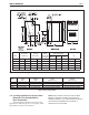
BRUTE MAGNUM Size “V” Vent Outlet Connection Page 7 “A” Air Inlet Connection “W” Water Inlet/ Outlet Connection “G” Gas Connects. Control Packages Std & A Nat/ LP B&E Nat B&E LP “B” inches inches NPT NPT NPT NPT inches 1200 6 6 2-1/2” 1’ 1-1/2’ 1-1/2” 34-1/4” 1600 6 8 2-1/2” 1-1/2’ 2” 2’ 34-1/4” 2000 7 8 3” 1-1/2’ 2” 2” 34-1/4” 2400 10 8 3” 1-1/2” 2” 2” 32” Figure 1. Dimensional Drawing. Size 1200 1600 2000 2400 Intake Size 6" (15 cm) dia. 8" (20 cm) dia.
BRADFORD WHITE CORP. Page 8 Section 2 VENTING AND COMBUSTION AIR 2.1 Combustion Air Brute Magnum boilers and water heaters must have provisions for combustion and ventilation air in accordance with the applicable requirements for Combustion Air Supply and Ventilation in the National Fuel Gas Code, ANSI Z223 1; or in Canada, the Natural Gas and Propane Installation Code, CSA B149.1. All applicable provisions of local building codes must also be adhered to.
BRUTE MAGNUM Term Description Pipe Single-wall galvanized steel pipe, 24 gauge minimum (sized per section 1.9) Joint Sealing Permanent duct tape or aluminum tape Insulation Not required, but recommended R5 insulation for cold installations (consult American Society of Heating, Refrigerating, and Air Conditioning Engineers (ASHRAE) handbook Table 4. Required Combustion Air Piping Material.
BRADFORD WHITE CORP. Page 10 U.S. Installations (see note 1) A= Clearance above grade, veranda, porch, 12 inches (30 cm) deck, or balcony B= Clearance to window or door that may be 4 feet (1.
BRUTE MAGNUM 1. 2. 3. 4. 5. 6. 7. The figure in this addendum shows the requirements for mechanical vent terminal clearances for the U.S. and Canada. Vent terminals for condensing appliances or appliances with condensing vents are not permitted to terminate above a public walkway, or over an area where condensate or vapor could create a nuisance or hazard. Locate the vent terminal so that vent gases cannot be drawn into air conditioning system inlets.
Page 12 (c) MANUFACTURER REQUIREMENTS – GAS EQUIPMENT VENTING SYSTEM PROVIDED. When the manufacturer of Product Approved side wall horizontally vented gas equipment provides a venting system design or venting system components with the equipment, the instructions provided by the manufacturer for installation of the equipment and the venting system shall include: 1. Detailed instructions for the installation of the venting system design or the venting system components; and 2.
BRUTE MAGNUM Page 13 At the time of removal of an existing boiler, the following steps shall be followed with each appliance remaining connected to the common venting system placed in operation, while the other appliances remaining connected to the common venting system are not in operation. 1. Seal any unused openings in the common venting system. 2.
BRADFORD WHITE CORP. Page 14 7. All threaded joints should be coated with piping compound resistant to action of liquefied petroleum gas. 8. The appliance and its individual shutoff valve must be disconnected from the gas supply piping during any pressure testing of that system at test pressures in excess of 1/2 PSIG (3.45kpa). 9.
BRUTE MAGNUM medium is piped in parallel with the boiler with appropriate valves to prevent the chilled medium from entering the boiler. The boiler piping system of a hot water heating boiler connected to heating coils located in air handling appliances where they may be exposed to refrigerated air circulation must be equipped with flow control valves or other automatic means to prevent gravity circulation of the boiler water during the cooling cycle.
Page 16 BRADFORD WHITE CORP. Figure 4. Hydronic Piping - Multiple Boilers. 4B.3 Water Flow Requirements — Water Heater In a water heating application (an open system), new water is constantly being introduced. With the new water comes a fresh supply of minerals that can be deposited on the unit’s heat exchanger. This is commonly known as scaling. The amount of minerals will depend upon the hardness of the water.
BRUTE MAGNUM Page 17 Figure 5. Hydronic Piping — Multiple Boilers (Alternate). If the water at the inlet of the copper heat exchanger is less than 140°F (60°C), water from the outlet of the copper heat exchanger will be directed back to the inlet of the copper heat exchanger, and will mix to bring the inlet water up to 140°F (60°C). Once through the copper heat exchanger, the water picks up another 20-25°F (11-14°C) (when at high fire), and it leaves the boiler at 160-165°F (71-74°C).
BRADFORD WHITE CORP. Page 18 Figure 6. Hydronic Piping — One Boiler, Multi-Temperature System. 4B.4 Combined Water (potable) Heating and Space Heating NOTE: These systems are not allowed in the Commonwealth of Massachusetts. Piping and components connected to this water heater for the space heating application shall be suitable for use with potable water. Toxic chemicals, such as used for boiler treatment, shall not be introduced into the potable water used for space heating.
BRUTE MAGNUM Page 19 4B.5 Freeze Protection – Water Heater Brute Magnum heaters are not designed to be placed outdoors, due to the potential for condensate to freeze in the unit. Power outage, interruption of gas supply, failure of system components, activation of safety devices, etc., may prevent a heater from firing.
Page 20 Figure 8. Water Heater Piping — One Heater, One Tank. BRADFORD WHITE CORP.
BRUTE MAGNUM Figure 9. Water Heater Piping — Multiple Heaters, One Tank.
Page 22 Figure 10. Water Heater Piping — One Heater, Multiple Tanks. BRADFORD WHITE CORP.
BRUTE MAGNUM Figure 11. Water Heater Piping — Multiple Heaters, Multiple Tanks.
BRADFORD WHITE CORP. Page 24 Section 5 ELECTRICAL CONNECTIONS WARNING The appliance must be electrically grounded in accordance with the requirements of the authority having jurisdiction or, in the absence of such requirements, with the latest edition of the National Electrical Code, ANSI/NFPA 70, in the U.S. and with latest edition of CSA C22.1 Canadian Electrical Code, Part 1, in Canada. Do not rely on the gas or water piping to ground the metal parts of the boiler.
BRUTE MAGNUM temperature is less than 140°F (60°C), internal mixing will keep the outlet temperature at 160-165°F (7174°C), and this will mix with the tank temperature to maintain a lower temperature in the tank. If the return temperature is 140°F (60°C) or higher, the outlet temperature of the heater will be the return temperature plus 20-25°F (11-14°C) when the Brute Magnum is at high firing rate. The manual reset high limit is on the outlet of the Brute Magnum.
Page 26 tank is drawing down, the heater will react to sustain a minimum tank temperature. Boilers generally have higher differentials than water heaters, to minimize short cycling (see throttling range). The differential is set by removing the cover of the A350 control and adjusting the potentiometer marked “DIFF” (see Figure 13). 5.5.3 Offset The offset determines the temperature below the controller’s setpoint where the throttling range begins. It offsets the throttling range.
BRUTE MAGNUM Page 27 Figure 15. Control Parameter Graph. 25% and 100% of full fire between 46°C and 49°C. Between 46°C and 49°C, the unit will remain at low fire. Between 38°C and 41°C, the unit will be at full fire. The throttling range is adjustable between 2°F and 30°F (1°C to 17°C). The range can be set by removing the cover of the S350P control and adjusting the “THROT RANGE” dial (see Figure 14). 5.5.5 Minimum Output Setting The minimum output setting of the controller is 0% of full fire.
Page 28 BRADFORD WHITE CORP. Figure 16. Control Parameter Possible Interference. changed. This setting will be the best suited to most Brute Magnum installations. Fast: Switch 4 to ON position and all others to OFF. If the rate of system recovery to setpoint is sluggish with the control set to medium, the “Fast” setting may be an improvement. The “Fast” setting will only be used when the rate of change at the sensor is very rapid. In most cases, this setting is too fast for the Brute Magnum. 5.
BRUTE MAGNUM Page 29 The second menu “Add” has to do with the N2 address. Pressing enter when “Add” is displayed will display “255”, which stands for 255 unique addresses. The up and down arrows change this value, and enter saves the value if it is changed. Changing the “Add” value will have no affect on the Brute Magnum, unless a communications card as been built onto the unit.
Page 30 Figure 17. Wiring Diagram, Size 1200, Standard and Codes A and F. BRADFORD WHITE CORP.
BRUTE MAGNUM Figure 18. Wiring Diagram, Sizes 1600, 2000 and 2400, Standard and Codes A and F.
Page 32 Figure 19. Wiring Diagram, Size 1200, Code B. BRADFORD WHITE CORP.
BRUTE MAGNUM Figure 20. Wiring Diagram, Sizes 1600, 2000 and 2400, Code B.
Page 34 Figure 21. Wiring Schematic, Model 1200, Standard and Codes A and F. BRADFORD WHITE CORP. Figure 22. Wiring Schematic, Models 1600, 2000 and 2400, Standard and Codes A and F.
BRUTE MAGNUM Figure 23. Wiring Schematic, Model 1200, Code B. Page 35 Figure 24. Wiring Schematic, Models 1600, 2000 and 2400, Code B.
Page 36 Section 6 OPERATING INSTRUCTIONS 6.1 Filling the Boiler System 1. 2. 3. 4. 5. 6. 7. 8. 9. 10. 11. 12. 13. Ensure the system is fully connected. Close all bleeding devices and open make-up water valve. Allow system to fill slowly. If make-up water pump is employed, adjust pressure switch on pumping system to provide a minimum of 12 psi (81.8 kPa) at the highest point in the heating loop.
BRUTE MAGNUM Page 37 5. 6. 7. 8. 9. 10. 11. Figure 25. Gas/Air Test Panel. 12. 13. 14. Valve Shown Closed 15. 16. 17. Valve Shown Open Figure 26. Test Panel Valves. panel are closed (see Figure 26). Remove the two plugs from the + and – ports of the air orifice taps, thread hose barbs into the 1/8" NPT connections, and attach the manometer pressure lines to the barbs. Be sure all connections are gas tight. Switch on the appliance power switch located on the front of the unit.
BRADFORD WHITE CORP. Page 38 (c) Open gas shutoff valve. Restart the appliance. The ignition sequence will start again and the burner will start. The appliance will return to its previous mode of operation. Caution Should any odor of gas be detected, or if the gas burner does not appear to be functioning in a normal manner, CLOSE MAIN SHUTOFF VALVE. Do not shut off switch. Contact your heating contractor, gas company, or factory representative.
BRUTE MAGNUM Figure 27. Gas Trains.
BRADFORD WHITE CORP.
BRUTE MAGNUM Page 41 shutoff valve. Remove the front and right-side panels from the unit. Disconnect the union between the valve body and the blower. Label the four pressure tubes that are connected to the valve actuator, to ensure that they will be replaced correctly. Remove the valve actuator, per the instructions above. Unscrew the valve body from the gas train. After the valve has been removed, replace with a new valve in the reverse order.
BRADFORD WHITE CORP. Page 42 7.2.10 Mixing Actuator The mixing actuator connects to both mixing valves and takes its signal from the mixing control to properly set the valves to protect the copper heat exchanger. To remove the actuator, remove the screw on the front to take the cover off. Disconnect the wires. Take the 2 nuts off the U-bolt, to move the linkage to the side, out of the way. Slide the actuator out. Reassemble in reverse order. 7.2.
BRUTE MAGNUM 8. Page 43 Clean the heat exchanger: A light accumulation of soot or corrosion on the outside of the heat exchanger can be easily removed. Use a wire brush to remove loose soot and scale from the heat exchanger. Do not use water or compressed air for cleaning. 9. NOTE: While the heat exchanger is out of the unit, inspect the firewall refractory insulation blocks for cracks, wear and breakage. Replace if necessary. 10. Inspect the inside of the copper tubes for scale buildup.
BRADFORD WHITE CORP. Page 44 6. When the call for heat is complete, or the unit reaches its setpoint temperature, the gas valve will close, and the fan will continue to run for its 30 second post-purge. If a pump time delay is used, the pump will continue to run for the specified amount of time (adjustable from 0.1 to 10 minutes). 8.2 Resolving Lockouts There are many causes of lockouts.
BRUTE MAGNUM 8.5 Short Cycling — Water Heater Short cycling will generally occur only in combination space heating and water heating applications when the water heater is operating in the space-heating mode. Because the Brute Magnum is a modulating water heater and its input will reduce when there is a reduction in heating load, short cycling is greatly reduced.
BRADFORD WHITE CORP. Page 46 9.
BRUTE MAGNUM 1200 50 Tubing/Fittings (gas train repair kit) R2020700 51 Air filter box assembly (with gasket and hardware) Nat 12B5000 51 Air filter box assembly (with gasket and hardware) LP 12B5020 52 Air filter A2108300 53 Gasket kit, air filter R2004600 54 Air filter box cover 24B5300 55 Air filter felt gasket S2010800 56 Air filter air inlet vent w / gasket 12B5001 57 Blower A2108500 58 Blower gasket kit R2012200 59 Air orifice, Nat 12B5108 60 Air orifice strip, LP not used 61 Air orifice, LP 12B512
BRADFORD WHITE CORP.
BRUTE MAGNUM Figure 30. Combustion Components.
Page 50 Figure 31. Gas Train/Combustion Air Components. BRADFORD WHITE CORP.
BRUTE MAGNUM Page 51 40 63 48 38 OR 40 36 41 (Primary) Standard and Control Pack F Gas Train 67 46 OR 47 49 39 OR 40 41 (Secondary) 50 38 OR 40 48 36 45 63 41 (Primary) Control Pack A Gas Train 67 46 OR 47 49 63 38 OR40 50 48 44 37 39 OR 40 41 (Secondary) 49 41 (Primary) Control Pack B Gas Train 49 37 63 38 OR 42 67 39 50 44 48 39 OR 40 46 OR 47 41 (Secondary) For sizes 1200, 1600 and 2000 Propane gas 67 46 OR 47 41 (Secondary) 42 OR 43 For sizes 2000 Natural gas and
Page 52 Figure 33. Electrical Components. BRADFORD WHITE CORP.
BRUTE MAGNUM Figure 34. Heat Exchanger / Water Path Components.
Page 54 Figure 35. Heat Exchanger / Water Path Components. BRADFORD WHITE CORP.
BRUTE MAGNUM Figure 36. Jacket Components.
H2343400- Bradford White Company reserves the right to change specifications, components, features, or to discontinue products without notice. Ambler, PA 19002 Tech. Service (800) 334-3393 Service Parts (800) 538-2020 Warranty Service (800) 531-2111 www.BradfordWhite.com Litho in U.S.A.