GAS-FIRED WATER HEATER A Spanish language version of these instructions is available by contacting the company listed on the rating plate. La versión española de estas instrucciones se puede obtener al scribirle a la fábrica cuyo nombre aparece en la placa de especificaciones.
CONGRATULATIONS! You have purchased one of the finest water heaters on the market today! This installation, operation and instruction manual will explain in detail the installation and maintenance of your new Flammable Vapor Ignition Resistant Gas Water Heater. We strongly recommend that you contact a plumbing professional for the installation of this water heater. We require that you carefully read this manual, as well as the enclosed warranty, and refer to it when questions arise.
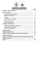
TABLE OF CONTENTS Page GENERAL INFORMATION ........................................................... 4 INSTALLATION ............................................................................ 5 Locating The Water Heater ................................................... 5 Minimum Clearances ............................................................. Venting ................................................................................... 8 9 Combustion Air Supply ..............................
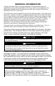
GENERAL INFORMATION This gas-fired water heater is design certified by CSA International under the applicable American National Standard, Z21.10.1 or CSA 4.1-(as indicated on the rating plate), available from CSA International, 8501 East Pleasant Valley Road, Cleveland, OH U.S.A. 44131-5575. This water heater must be installed in accordance with local codes. In the absence of local codes, it must be installed in compliance with the National Fuel Gas Code (ANSI Z223.
General Information cont.This water heater has been manufactured for operation at altitudes from sea level to 2000 ft (610 m) (unless otherwise specified on the water heater rating plate). For use of this appliance at an elevation greater than 2000 ft (610 m), contact the dealer or manufacturer listed on the rating plate for information on any necessary modification. Incorrect operation of this appliance may create a hazard to life and property.
Installation (Locating the Water Heater) cont.- This water heater MUST be installed indoors out of the wind and weather. To comply with NSF requirements this water heater is to be: a) Sealed to the floor with sealant, in a smooth and easily cleanable way, or b) Installed with an optional leg kit that includes legs and/or extensions that provide a minimum clearance of 6” beneath the water heater.
Installation (Locating the Water Heater) cont.- Proper venting practices must be considered when selecting a location for this water heater. For exact venting specifications, please consult the Venting section of these Installation and Operation Instructions.
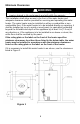
Minimum Clearances WARNING Failure to adhere to these installation and operating instructions may create a hazard to life and property and will nullify the warranty. This installation shall allow access to the front of the water heater and adequate clearance shall be provided for servicing and operating this water heater. The water heater may be installed on either a combustible or noncombustible floor.
Venting WARNING The venting system must be installed properly following all local codes or in the absence of local codes, the latest edition of the National Fuel Gas Code (ANSI Z223.1- latest edition), or in Canada, The Natural Gas and Propane Installation Code (B149.1-00 latest edition). Failure to properly install the venting system could result in property damage, personal injury, or death.
Combustion Air Supply WARNING Liquefied petroleum gases/propane gas are heavier than air and will remain at floor level if there is a leak. Basements, crawl spaces, closets and areas below ground level will serve as pockets for accumulation of leaking gas. Before lighting, smell all around the appliance area for gas. Be sure to smell next to the floor. IF YOU SMELL GAS: • DO NOT try to light any appliance. • DO NOT touch any electric switch; DO NOT use any telephone in your building.
Combustion Air Supply cont.- All Air from Outdoors: Provide two permanent openings, one commencing within 12 in (30 cm) of the top and one commencing within 12 in (30 cm) from the bottom of the enclosure. The openings must communicate directly or by ducts with the outdoors or spaces (crawl or attic) that freely communicate with the outdoors. 1.
Installation (Water Connections) continued- If this water heater is installed in a closed water supply system, such as the one having a back-flow preventer in the cold-water supply, provisions shall be made to control thermal expansion. DO NOT operate this water heater in a closed system without provisions for controlling thermal expansion.
Installation (Water Connections) continued- WARNING Hydrogen gas can be produced in an operating water heater that has not had water drawn from the tank for a long period of time (generally two weeks or more). HYDROGEN GAS IS EXTREMELY FLAMMABLE. To prevent the possibility of injury under these conditions, we recommend the hot water faucet to be open for several minutes at the kitchen sink before you use any electrical appliance, which is connected to the hot water system.
Gas Connections cont.- 1. Connect this water heater only to the type of gas (Natural or Propane) as shown on the rating plate. Use clean black iron pipe or equivalent material approved by local codes and ordinances (dirt and scale from the pipe can enter the gas valve and cause it to malfunction). The inlet gas line must have a minimum length of 3 in (7.6 cm) drip leg (sediment trap) installed as close to the water heater’s gas valve as possible.
GENERAL OPERATION WARNING Water heaters are heat producing appliances. To avoid damage or injury there shall be no materials stored against the water heater or vent-air intake system, and proper care shall be taken to avoid unnecessary contact (especially by children) with the water heater and vent-air intake system.
Lighting & Shutdown Instructions- White Rodgers Mechanical Gas Control 16
Lighting & Shutdown- White Rodgers Electronic Gas Control 17
Lighting & Shutdown- Honeywell Gas Control 18
Thermostat Adjustment - White Rodgers Mechanical Gas Control Figure 2 Figure 3 Thermostat Adjustment – White Rodgers Electronic Gas Control Figure 4 Figure 5 19
General Operation continued- Thermostat Adjustment- Honeywell V1 Gas Control Figure 6 Figure 7 Thermostat Adjustment- Honeywell V2 Gas Control Figure 8 Figure 9 20
WARNING Hotter water increases the risk of scald injury. Scalding may occur within 5 seconds at a temperature setting of 140F (60C). To protect against hot water injury, install an ASSE approved mixing valve in the water system. This valve will reduce point of discharge temperature by mixing cold and hot water in branch water lines. A licensed plumbing professional or local plumbing authority should be consulted. Note: This water heater is equipped with an energy cut out device to prevent overheating.
MAINTENANCE WARNING Water heaters are heat producing appliances. To avoid damage or injury there shall be no materials stored against the water heater or vent-air intake system, and proper care shall be taken to avoid unnecessary contact (especially by children) with the water heater and vent-air intake system.
Maintenance continued- WARNING • DO NOT operate water heater with jumpered, altered, loosely tightened or absent controls and/or components. • DO NOT operate water heater with replacement controls and/or components, which are not exact duplicates or original equipment. • Thoroughly inspect and replace, (as needed) burner inner door gasket and/or sight window gasket any time burner inner door is removed or disturbed. • Replace water heater if involved in flammable vapors incident.
Troubleshooting Chart – Honeywell V1 LED Status Control Status None (LED not on or flashing) Millivolt power is not present. Light pilot. Probable Cause 1. Gas valve is functioning normally. 2. Gas valve is not powered. Light pilot. One flash and three second pause If set point knob is in “PILOT” position, then pilot flame is detected. (no faults). Gas valve is powered and waiting for the set point knob to be turned to a water temperature setting.
Troubleshooting Chart – Honeywell V1 continued- LED Status Control Status Probable Cause Five flashes and three second pause Temperature sensor fault. 1. Damage to the temperature wire. 2. Temperature sensor resistance out of range. 3. Replace temperature sensor. 4. If temperature sensor replacement does not correct the problem; verify control is not wet or physically damaged. 5. Turn set point knob to "OFF" position. Turn set point knob to "PILOT" position and light pilot. 6.
Troubleshooting Chart – Honeywell V2 LED Status Control Status Probable Cause None (LED not on or flashing) Not an error. Indicates control is in OFF mode. Pilot is off. Gas valve is functioning normally. Gas valve is not powered. Light pilot. One flash every four seconds (LED green) Not an error. Indicates pilot is lit and main burner is off. The knob can be turned to a desired setpoint temperature. One flash every second (LED green) Not an error.
Troubleshooting- White Rodgers Electronic LED Status Control Status Probable Cause None (LED not on or flashing) Indicates control is off. Main and pilot burner are off. Gas valve is functioning normally. Gas valve is not powered. Light pilot. One flash every four seconds Not an error. Indicates pilot is lit and main burner is off. Gas valve is powered and waiting for the set point knob to be turned to a water temperature setting.
Troubleshooting continued- CAUTION FOR YOUR SAFETY, DO NOT ATTEMPT REPAIR OF COMBINATION GAS CONTROL, BURNERS OR GAS PIPING. REFER REPAIRS TO A QUALIFIED SERVICE TECHNICIAN. Contact your supplier or plumbing professional for replacement parts or contact the company at the address given on the rating plate of the water heater. Provide the part name, model and serial numbers of the water heater when ordering parts.
INSTALLATION FOR POTABLE WATER Figure 11 29
PARTS DIAGRAM PART NAME AND DESCRIPTION 1. Draft Diverter 2. Jacket Head Pan 3. Jacket 4. Outer Door 5. Magnesium Anode– Hot Water Outlet 6. Flue Baffle Assembly 7. Dip Tube–Cold Water Inlet 8. Temperature and Pressure Relief Valve 9. Glass Lined Tank 10. Combustion Chamber Assembly 11. Jacket Base Pan 12. Inner Door Gasket 13. Inner Door Assembly 13A. High temperature limit switch 14. Drain Valve 15. Piezo Igniter – Use with White Rogers Gas Control 16A. Gas Control Valve – Honeywell 16B.
THE FOLLOWING INSTRUCTIONS ARE FOR INSTALLATION OF: GAS WATER HEATERS SUITABLE FOR WATER (POTABLE) HEATING AND SPACE HEATING 1. All piping components connected to this water heater for space heating applications must be suitable for use with potable water. In Massachusetts, space heating piping length must NOT exceed 50 ft. 2. Toxic chemicals, such as those used for boiler treatment, must NOT be introduced into potable water used for space heating. 3.
NOTES 32