
Service Manual


GENERAL INFORMATION
Page 11
11
Sequence of Operation
This water heater has two distinct electrical systems. One system, referred to as the “Control Circuit”, controls
the water heater operation, while the other system, referred to as the “Power Circuit”, connects the electrical
power to the heating elements. The electrical contactors interconnect these two systems. In order to clearly
illustrate the electrical circuits, two wiring diagrams are provided. These diagrams are labeled as the “Control
Circuit Wiring Diagram” and the “Power Circuit Wiring Diagram” and they are attached to the surface of the
panels inside the water heater control cabinet.
Control Circuit Description
The control circuit operates with 120VAC electrical service. This voltage is provided by the multi-tap transformer
which has the primary coil connected to the field wiring that is serving the water heater. The Transformer,
Thermostat, High-Limit control, and the Contactor Coil are always included in the Control Circuit.
Certain other control components are available as “Optional“. When these optional components are installed
with the water heater, the control circuit wiring diagram accordingly will include these components. The
optional equipment available from the manufacturer includes the following:
High Water Pressure Switch
Low Water Pressure Switch
Low Water Level Switch
Alarm Horn
Heating Element Sequencers
Electrical Door Lock
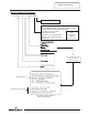
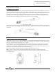
Control Circuit Sequence of Operation
Line voltage is applied to control circuit fuse block.
Line voltage continues to transformer with one leg of
voltage connecting to the common terminal and the
other leg connecting to the appropriate line voltage
multi-tap terminal. Transformer output (always 120
volts) continues to high limit (ECO) control.
Hi-limit (ECO) control is closed so one leg of 120 volts
continues to one side of the contactor coil. The other
leg is connected to the thermostat.
When the thermostat calls for heat, contacts close
inside the thermostat, then completing the circuit and
energizing the contactor coil.
The energized contactor coil causes the contactor to
close, energizing the heating elements.
When the temperature setting of the thermostat is
reached, the contacts in the thermostat open. This
interrupts current flow through the control circuit,
de-energizing the contactor coil.
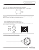
Control Circuit Wire Diagram
The de-energized contactor coil causes the contactor to open,
interrupting current flow through the heating elements.
Line voltage from power circuit
Appropriate line voltage
mulƟ-tap terminal
NOTE: To help understand the concept of the
operating sequence, the control circuit shown is
without any optional controls. See page 11 for
control circuit showing all available optional controls.
10
10