ASME COMMERCIAL ELECTRIC WATER HEATER A Spanish language version of these instructions is available by contacting the company listed on the rating plate. La versión espãnola de estas instructiones se puede obtener al escribible a la fábrica cuyo nombre aparece en la placa de especificaciones. INSTALLATION & OPERATING INSTRUCTION MANUAL THE WARRANTY ON THIS WATER HEATER IS IN EFFECT ONLY WHEN THE WATER HEATER IS INSTALLED AND OPERATED IN ACCORDANCE WITH LOCAL CODES AND THESE INSTRUCTIONS.
TABLE OF CONTENTS General Information .......................................................... Page 3 Installation ......................................................................... 4 Locating The Water Heater............................................... 4 Water Connections ............................................................ 5 Electrical Connections ...................................................... 12 Amperage Chart...........................................................
General Information This electric water heater’s design is certified by Intertek (ETL) and listed in accordance with UL 1453. C-UL listed in accordance with Canadian National Standard C22.2, No. 110-M90. This water heater must be installed in accordance with local codes. In the absence of local codes, install this water heater in accordance with the latest edition of the National Electrical Code.
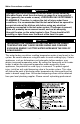
Installation Locating The Water Heater WARNING Water heaters are heat producing appliances. To avoid damage or injury, there shall be no materials stored against the water heater and proper care shall be taken to avoid unnecessary contact (especially by children) with the water heater. UNDER NO CIRCUMSTANCES SHOULD FLAMMABLE MATERIALS, SUCH AS GASOLINE OR PAINT THINNER BE USED OR STORED IN THE VICINITY OF THIS WATER HEATER OR ANY LOCATION FROM WHICH FUMES COULD REACH THE WATER HEATER.
Clearances 1. Minimum clearance to combustible material is 0 in for the top, sides, front, and rear of this water heater. However, it is recommended that there is at least 18 in (45.7 cm) from the top and 24 in (61 cm) from the front. Clearance for servicing may be reduced down to minimum clearance to combustible material, but service time and effort may be greatly increased. 2. Increase distances to provide clearances for servicing. This water heater MUST be installed indoors out of the wind and weather.
Installation (Water Connections) continued- After installation of the water lines, open the main water supply valve and fill the water heater. While the water heater is filling, open several hot water faucets to allow air to escape from the water system. When a steady stream of water flows through the faucets, close the faucets and inspect all water connections for possible leaks. NEVER OPERATE THE WATER HEATER WITHOUT FIRST BEING CERTAIN IT IS COMPLETELY FILLED WITH WATER.
Water Connections continued- WARNING Hydrogen gas can be produced in the hot water system served by this water heater when there has been no usage for a long period of time (generally two weeks or more). HYDROGEN GAS IS EXTREMELY FLAMMABLE. Therefore, to reduce the risk of injury under these conditions, it is recommended that the hot water faucet be opened for several minutes at the kitchen sink before using any electrical appliance connected to the hot water system.
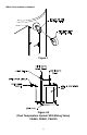
Water Connections continued- Figure 1 Figure 2A (Dual Temperature System With Mixing Valve) CEA50, CEA80, CEA120 8
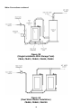
Water Connections continued- Figure 2B (Dual Temperature System With Mixing Valve) CEA6, CEA12, CEA 20, CEA30, CEA40 Figure 3A (Single Installation With Storage Tank) CEA50, CEA80, CEA120 9
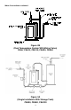
Water Connections continued- Figure 3B (Single Installation With Storage Tank) CEA6, CEA12, CEA20, CEA30, CEA40 Figure 4A (Dual Water Heater Installation) CEA50, CEA80, CEA120 10
Water Connections continued- Figure 4B (Dual Water Heater Installation) CEA6, CEA12, CEA20, CEA30, CEA40 11
Electrical Connections Before any electrical connections are attempted, be sure the water heater is full of water and that the manual shut-off valve in the cold water supply line is open. Heating elements, which have been energized for a very short period of time, can be damaged (burned-out) if they are not completely immersed in water. This warranty DOES NOT cover burned-out heating elements. Check the rating plate and wiring diagram before proceeding.
Amperage Chart kW Input 3 6 9 12 13.
General Operation Before closing the switch to allow electric current to flow to the water heater, make certain that the water heater is full of water and that the cold water inlet valve is open. Complete failure of the heating elements will result if they are not totally immersed in water at all times. When the switch is closed, the operation of this electric water heater is automatic. The temperature control knob located on the side on the control box is factory preset to 120°F (49°C).
Thermostat Adjustment continued- DANGER Hotter water increases the risk of scald injury. Scalding may occur within five (5) seconds at a temperature setting of 140°F (60°C). To protect against hot water injury, install an anti-scald tempering valve in the water system. This valve will reduce point of discharge water temperatures by mixing cold and hot water in branch water lines. A licensed plumbing professional or local plumbing authority should be consulted.
Maintenance continued- The following maintenance should be performed by a qualified service technician at the minimum periodic intervals suggested below. In some installations, the maintenance interval may be more frequent depending on the amount of use and the operating conditions of the water heater. Regular inspection and maintenance of the water heater will help to insure safe and reliable operation. 1. Annually, check the operation of the thermostat(s). 2.
Maintenance continued- CAUTION FOR YOUR SAFETY, DO NOT ATTEMPT TO REPAIR THERMOSTAT(S), HEATING ELEMENTS, OR ELECTRICAL WIRING. REFER SUCH REPAIRS TO A QUALIFIED SERVICE TECHNICIAN. Contact your local plumbing supplier or plumbing professional for replacement parts or contact the company at the address displayed on the rating plate of the water heater. For faster and better service, please provide the part name, model, and serial number(s) of the water heater(s) when ordering parts.
Servicing Guide This “Servicing Guide” section of this Installation and Operation Installation manual is provided for the purpose of improving the effectiveness and the efficiency of servicing this water heater. This information is intended to assist qualified service personnel. Servicing of this water heater may require knowledge of electrical testing instruments. If you are unfamiliar or unsure of the electrical circuits or the testing instruments, consult a qualified electrician.
Servicing Guide continued- Optional Components High and Low Water Pressure Controls These controls interrupt the electrical current to the contactor coil when the pressure settings are exceeded. The operation and setting of these controls are described in the manual provided by the control manufacturer. This manual is included with the water heater Installation and Operating Instruction manual provided by the manufacturer. The pressure settings for these controls are adjustable.
Servicing Guide continued- Figure 6 When installing the control refer to the direction of the arrow on the hex and insure that it is pointing upwards. If it is not pointing upward, the control switch will not activate when the tank is refilled with water. Refer to Figure 7 for clarification. Figure 7 Alarm Horn The Alarm Horn is an option specified when the installation desires an audible signal to immediately sound an alert when the water heater operation is interrupted for certain faults.
Servicing Guide continued- The following unusual situations will give reason for the alarm to sound: If a High Pressure Control is installed, upon installation of the water heater or occasions of re-starting water heater operation, if the inlet supply line is closed (i.e. a shut-off valve), the high pressure may be exceeded due to reasons of thermal expansion of the water. If a Low Pressure Control is installed and if during the operation of the water heater the inlet line is closed (i.e.
Servicing Guide continued- Power Circuit Description The Power Circuit Wiring Diagram illustrates the electrical connections from the incoming power supply through the circuit to the electrical elements. The power circuits are available with internal circuit fusing and without internal circuit fusing. Refer to the water heater power circuit wiring diagram attached to the inside panel of the control cabinet for the specific connections of the water heater being serviced.
NOTES 23
NOTES 24