GAS-FIRED COMMERCIAL WATER HEATER WARNING: If the information in these instructions is not followed exactly, a fire or explosion may result causing property damage, personal injury or death. - Do not store or use gasoline or other flammable vapors and liquids in the vicinity of this or any other appliance. - WHAT TO DO IF YOU SMELL GAS • Do not try to light any appliance. • Do not touch any electrical sw itch; do not use any phone in your building.
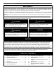
SECTION I: IMPORTANT INFORMATION READ CAREFULLY This gas-fired w ater heater is design certified by CSA International under the American National Standard, Z21.10.3 and CAN/CGA 4.3-M (as indicated on the rating plate). These standards are available from CSA Standards Association, 5060 Spectrum Way Mississauga, Ontario L4W 5N6 CANADA. This w ater heater must be installed in accordance w ith local codes.
DANGER DO NOT store or use gasoline or other flammable, combustible, or corrosive vapors and/or liquids in the vicinity of this or any other appliance. This water heater is equipped with an adjustable thermostat to control water temperature. Hot water temperatures required for automatic dishwasher and laundry use can cause scald burns resulting in serious personal injury and/or death. The temperature at which injury occurs varies with the person’s age and the time of exposure.
WARNING This water heater needs fresh air for safe operation and must be installed so there are provisions for adequate combustion and ventilation air. Insufficient air supply will cause a recirculation of combustion products resulting in contamination that may be hazardous to life. This will result in carboning or sooting of the combustion chamber, burners, and flue tubes and creates a risk of asphyxiation.
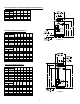
SECTION II: SPECIFICATIONS Non-Flue Damper Models and Flue Damper Models (Figure 1) Model Description Capacity Input (BTU/hr) (GAL) Nat. LP 100 199,999 199,999 100 250,000 250,000 100 270,000 N/A 100 300,000 300,000 80 399,999 375,000 80 450,000 425,000 80 505,000 475,000 A (in) B (in) C (in) 75.00 75.00 75.00 75.44 71.50 69.00 69.00 64.75 64.75 64.75 64.75 60.25 60.25 60.25 56.50 56.50 56.50 56.50 51.50 51.50 51.50 Model Description A Capacity Input (kW/hr) (cm) (Litres) Nat. LP 378.5 58.6 58.6 378.
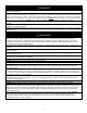
Flue Damper Models and Non-Flue Damper Models (Figure 3) Model Description Capacity Input (GAL) (BTU/hr) 38 155,000 Model Description Capacity Input (Litres) (kW/hr) 143.9 45.4 E (in.) A (in.) B (in.) C (in.) D (in.) 51.00 43.50 35.00 33.75 6 A (cm) B (cm) C (cm) D (cm) E (cm) 130 110 89 86 15.2 Non-Flue Damper Models (Figure 4) Model Description Cap.
Non-Flue Damper Models (Figure 5) Model Description Capacity Input (GAL) (BTU/hr) 75 B (in.) C (in.) D (in.) E (in.) 67.13 65.00 54.50 6 A (cm) B (cm) C (cm) D (cm) E (cm) 178 171 165 138 15.2 160,000 (155,000 70.13 LP) Model Description Capacity Input (Liters) (kW/hr) 283.9 A (in.) 46.9 (45.4 LP) Flue Damper Models (Figure 5) Model Description Capacity Input (GAL) (BTU/hr) A (in.) B (in.) C (in.) D (in.) E (in.) 75 125,000 72.25 67.13 65.00 54.
SECTION III: GENERAL INFORMATION FEATURES 1. 2. 3. 4. 5. Porcelain enamel lined tank provides corrosion protection with a tough glass lining on the interior of the tank. Magnesium anodes provide an extra measure of protection and extends tank life. Flue Damper on 24 volt ignition models reduces standby losses on the burner off cycle saving fuel. Hand Hole Cleanout allows inspection of tank interior and allows the removal of lime and sediment deposits.
DISHWASHING MACHINE REQUIREMENTS All dishwashing machines meeting the National Sanitation Foundation requirements are designed to operate with water flow pressures between 15 and 25 pounds per square inch. Flow pressures above 25 pounds per square inch, or below 15 pounds per square inch, will result in improperly sanitized dishes. The National Sanitation Foundation also recommends circulation of 180°F water.
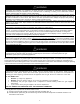
SECTION IV: INSTALLATION INSTRUCTIONS WARNING INSTALLATION OF THIS WATER HEATER REQUIRES ABILITY EQUIVALENT TO THAT OF A LICENSED TRADESMAN IN THE FIELD INVOLVED. PLUMBING, AIR SUPPLY, VENTING, GAS SUPPLY AND ELECTRICAL WORK ARE REQUIRED. DO NOT ATTEMPT TO LIGHT ANY GAS APPLIANCE IF YOU ARE NOT CERTAIN OF THE FOLLOWING: • Liquefied petroleum gases/propane gas and natural gas have an odorant added by t he gas supplier that aids in detection of the gas.
Minimum Clearances CAUTION The National Fuel Gas Code (ANSI Z233.1- latest edition) or in Canada The Natural Gas or Propane Installation Code CAN/CGA (B149.1, B149.2- latest edition), expressly prohibits the following: a. Installation of a w ater heater in a bathroom, bedroom, or any occupied room normally kept closed. b. Installation of a w ater heater in a garage, unless the unit is installed so that the burner and ignition devices are at least eighteen (18) inches (45.
UNPACKING INSPECT SHIPMENT carefully for any signs of damage. 1. All equipment is carefully manufactured, inspected and packed. 2. Any claims for damage or shortage in shipment must be filed immediately with the manufacturer noted on the rating plate label. LOCATE WATER HEATER in front of final position before removing crate. 1. LOCATE so that venting connections will be short and direct. 2. THIS WATER HEATER IS SUITABLE FOR INSTALLATION ON COMBUSTIBLE FLOOR.
REMOVE CRATE 1. Remove all banding and pry off crate sides carefully so as not to damage the water heater. 2. Carefully roll/lift the water heater from the crate base. MOVE WATER HEATER TO PERMANENT POSITION by sliding or walking. Place drain pan underneath water heater INSTALL TEMPERATURE AND PRESSURE RELIEF VALVE (if not already installed). This water heater must be located in an area where the general public does not have access to set temperatures. AIR REQUIREMENTS 1.
ALL AIR FROM INSIDE THE BUILDING: The confined space must be provided with two permanent openings communicating directly with an additional room(s) of sufficient volume so that the combined volume of all spaces meets the criteria for an unconfined space. The total input of all gas utilization equipment installed in the combined space must be considered in making this determination. Each opening must have a minimum free area of 1 in.2/1000 BTU (2.54cm2/0.
SECTION V: VENTING WARNING The venting system must be installed properly follow ing all local codes or in the absence of local codes, the latest edition of the National Fuel Gas Code (ANSI Z223.1- latest edition), or in Canada, The Natural Gas and Propane Installation Code (B149.1-00 latest edition). Failure to properly install the venting system could result in property damage, personal injury, or death.
3. Secure the flue damper to the jacket top with sheet metal screws. 4. Connect the damper wiring plug to the damper wire harness connector on the side of the water heater. Note: The plug and connector can only be engaged one way (polarized). 5. The Lighting and Operating instructions are outlined in this manual. The damper must be in the open position when the water heater main burner is operating (the arrow on the damper plate is in the “up” position when open.
SECTION VI: WATER CONNECTIONS NOTE: BEFORE PROCEEDING WITH THE INSTALLATION, CLOSE THE MAIN WATER SUPPLY VALVE. After shutting off the main water supply, open a faucet to relieve the water line pressure to prevent any water from leaking out of the pipes while making the water connections to the water heater. After the pressure has been relieved, close the faucet. The COLD water inlet and HOT water outlet are identified on the top and front of the water heater.
WARNING Keep clear of combination temperature and pressure relief valve discharge line outlet. The discharge may be hot enough to cause scald injury. The water is under pressure and may splash.
SECTION VII: GAS CONNECTIONS The gas supply lines must meet all requirements of the National Fuel Gas Code (ANSI Z223.1-Latest Edition), or in Canada CAN/CGA B149.1 Natural Gas Installation Code (Latest Edition) or CAN/CGA B149.2 Propane Installation Code (Latest Edition). The minimum permissible gas supply pressure for the purpose of input adjustment is one (1.0) inch (0.25 kPa) water column above the operating manifold pressure. See the rating plate and gas valve for the manifold pressure and gas type.
WARNING Water heaters are heat-producing appliances. To avoid damage or injury there must be no materials stored against the water heater or direct vent system, and proper care must be taken to avoid unnecessary contact (especially by children) with the water heater and direct vent system. UNDER NO CIRCUMSTANCES SHOULD FLAMMABLE MATERIALS, SUCH AS GASOLINE OR PAINT THINNER BE USED OR STORED IN THE VICINITY OF THIS WATER HEATER OR IN ANY LOCATION FROM WHICH FUMES COULD REACH THE WATER HEATER.
SECTION VIII: ELECTRICAL CONNECTIONS Standing pilot Standing Pilot Wiring Diagram Robertshaw Gas Valve Honeywell Gas Valve Spark to Pilot (IID) ignition system. WARNING Turn off or disconnect the electrical power supply to the water heater before servicing. Label all wires prior to disconnection when servicing controls. Wiring errors can cause improper and dangerous operation. Verify proper operation after servicing.
Spark to Pilot Ignition (IID) Wiring Diagram 22
SECTION IX: OPERATING INSTRUCTIONS Lighting And Shutdown Instructions Standing Pilot Models 23
Lighting and Shutdown Instructions Spark to Pilot Ignition (IID) Models 24
TEMPERATURE ADJUSTMENT APPROXIMATE TIME/TEMPERATURE RELATIONSHIPS IN SCALDS 120° F (49° C) More than 5 minutes 125° F (52° C) 1½ to 2 minutes 130° F (54° C) About 30 seconds 135° F (57° C) About 10 seconds 140° F (60° C) Less than 5 seconds 145° F (63° C) Less than 3 seconds 150° F (66° C) About 1½ seconds 155° F (68° C) About 1 second DANGER Hotter water increases the risk of scald injury. Scalding may occur within five (5) seconds at a temperature setting of 140°F (60°C).
your needs. NOTE: This water heater, when set at a lower temperature setting, is not capable of producing hot water of sufficient temperature for sanitizing purposes. During the winter season or any cold period, you may desire a higher temperature setting to adjust for the colder incoming water. This adjustment, however, may cause additional condensation to form on the cooler tank surface. This does not mean the tank is leaking.
To Increase Setpoint Temperature Step 1: Depress and hold “Temperature Up” button until desired setpoint temperature appears in the display. °F idle Status Operational SELECT SET Step 1 Step 2: “Setpoint” indicator begins flashing in the display after pressing “Temperature Up” button. "Setpoint" flashes °F setpoint idle Status Operational SELECT SET Step 2 Step 3: Press “SET” button for new setting to take effect immediately. “Setpoint” will stop flashing.
To Decrease Setpoint Temperature Step 1: Depress and hold “Temperature Down” button until desired setpoint temperature appears in the display. °F idle Status Operational SELECT SET Step 1 Step 2: “Setpoint” indicator begins flashing in the display after pressing “Temperature Down” button. "Setpoint" flashes °F setpoint idle Status Operational SELECT SET Step 2 Step 3: Press “SET” button for new setting to take effect immediately. The setpoint will stop flashing.
To Change Temperature Format in Display from °F to °C or ˚C to ˚F: Step 1: Press “SELECT” button until °F/°C is displayed. °F °F/°C idle Status Operational SELECT Press select SET Step 1 Step 2: Press “SET” button to change temperature format. Symbol °F/°C will flash. °F °F/°C idle Status Operational SELECT SET °F/°C Flashes Step 2 Step 3a: Press “Temperature Up” button to change temperature format to °C.
Step 3b: Press “Temperature Down” button to change temperature format to °F. Changes to "°F" °F/°C Flashes °F °F/°C idle Status Operational SELECT SET Step 3b Step 4: Press “SET” button to confirm ˚F or ˚C format. °F/°C will stop flashing. Setpoint display will appear in the format selected (˚F or ˚C) in 10 seconds.
An automatic gas shut-off device (ECO) is incorporated in the sensor and control board which will shut off all gas supply to the burner and pilot if the water heater temperature exceeds 200°F (93°C). Should the ECO function (open), the water temperature should be reduced to approximately 120°F (49°C) and follow applicable Lighting Instructions to place the water heater in operation.
SECTION X: MAINTENANCE The following maintenance should be performed by a qualified service technician at the minimum periodic intervals suggested below. In some installations, the maintenance interval may be more frequent depending on the amount of use and the operating conditions of the water heater. Regular inspection and maintenance of the water heater will help to insure safe and reliable operation. 1.
Contact your supplier, plumbing professional or contact the company at the address given on the rating plate of the water heater for replacement parts. Provide the part name as well as the model and serial number(s) of the water heater(s) when ordering parts. READ THE WARRANTY FOR A FULL EXPLANATION OF THE LENGTH OF TIME THAT PARTS AND THE WATER HEATER ARE WARRANTED. Manufactured under one or more of the follow ing U.S.
SECTION XI: DIAGNOSTIC AND TROUBLESHOOTING GUIDE OPERATING AND TROUBLESHOOTING GUIDE-SEQUENCE OF OPERATION (STANDING PILOT WITH MILLI-VOLT CONTROL) 1. With the pilot lit, the pilot burner assembly power pile generates milli-voltage to energize the magnet coil in the gas valve permitting gas flow through pilot and to the main gas ports of the valve. Simultaneously, milli-voltage is also directed to the ECO (energy cut off) switches located in the thermostat. 2.
ACCESSING SERVICE MODE ON THE WATER HEATER DISPLAY (FOR SERVICE PERSONNEL ONLY) The display has a “service mode” for changing the maximum setpoint and accessing information in aiding servicing of the water heater. This procedure is for service and installation personnel only. To enter the Service Mode, follow the steps illustrated below: WARNING The following procedure is for service and installation personnel only.
The following is the sequence of modes available in “Service Mode” by pressing the “Select” button: Error Code Number (Display/Reset). This is only shown if there is an operating error in the “User Mode”. Error Code Shown in Water Heater Display Status Service Needed SELECT Lockout RESET 1. Max Setpoint (Display/Change) Max Setpoint value in Water Heater Display °F Max Setpoint idle Status Operational SELECT SET 2a.
2b. Water Temperature - Upper Sensor (Displays if there is an upper sensor – some models) °F idle Status Operational Upper Sensor SELECT SET 2c. Water Temperature - Lower Sensor (Displays if there are two sensors) °F idle Status Operational Lower Sensor SELECT SET 3.
4. Setpoint (Display/Change) °F setpoin t idle Status Operational SELECT SET 5. ˚F/˚C (Display/Change) °F °F/C° idle Status Operational SELECT SET 6.
7. Software Version (Display only) Soft idle Status Operational SELECT SET 8. Error Code History (Displays if there are present error codes or up to 10 previous error codes). Water Heater Display will show -- if there are no error codes.
Step 2: Press “Set” button to enter setting mode. “Max Setpoint” will flash to indicate setting mode. "Max Setpoint" Flashes °F Max Setpoint idle Status Operational SELECT SET Step 3: Press the “UP” or “DOWN” buttons to change the maximum setpoint value. This will limit the maximum setpoint the user can select. Note: The maximum setpoint is approximately 180˚F.
Step 5: 30 Seconds after the last button press, the Water Heater Display will go back to “User Mode”. It will read “Max Setpoint” without showing a temperature value if the temperature setpoint is at the maximum setting. The Water Heater Display can be set back to the “User Mode” immediately by pressing both the “Temperature Up” and “Select” buttons together for 3 seconds.
Step 2: For water heaters using two temperature sensors, pressing the “Select” button again displays the Upper Sensor temperature reading. “Upper Sensor” will be displayed in the lower right side of the status window of the water heater display. °F idle Status Operational Upper Sensor SELECT SET Step 3: For water heaters using two temperature sensors, pressing the “Select” button again displays the Lower Sensor temperature reading.
To Display and Change Temperature Setpoint: Step 1: In “Service Mode” press the “Select” button until “Setpoint” is shown in the water heater display. °F setpoint idle Status Operational SELECT SET Step 2: Press the “Set” button to enter the setting mode. “Setpoint” will flash in the water heater display.
Step 4: To lower the temperature setpoint, press the “Temperature Down” button until the desired temperature is shown on the water heater display. "Setpoint" Flashes °F setpoint idle Status Operational SELECT SET Step 5: When the desired setpoint is reached on the water heater display, press the “Set” button to confirm the new setpoint. “Setpoint” stops flashing in the water heater display.
Step 2: Press “Set” button to change temperature format. “˚F/˚C” symbol will flash in the water heater display. "°F/°C" Flashes °F °F/C° idle Status Operational SELECT SET Step 3a: Press “Temperature Up” button to change temperature format to ˚C. Changes to "°C" "°F/°C" Flashes °C °F/C° idle Status Operational SELECT SET Step 3b: Press “Temperature Down” button to change temperature format to ˚F.
Step 4: Press “Set” button to confirm ˚F or ˚C format. ˚F/˚C will stop flashing. "°F/°C" Symbol Stops Flashing °F °F/C° idle Status Operational SELECT SET Step 5: Pressing “Select” button will return display to setpoint in format selected (˚F or ˚C) immediately.
How to reset the control from Lockout Conditions: WARNING The following procedure is for service and installation personnel only. Resetting lockout conditions without correcting the malfunction can result in a hazardous condition. If an error code is displayed (except for #4, low flame sense current), the water heater will be in a “lockout condition” with the water heater display showing the error code number and “Service Needed” in the status section of the display window.
Error Codes and Error History Display: If there is an operating problem with the water heater, an error code number will appear on the water heater display with “Service Needed” to the right of the “Status” indicator. The error code label is located below the water heater display and the following section in this Installation and Operating Instruction Manual explains the error codes with corrective actions to repair the water heater.
Step 2: Press the “Temperature Down” button to select the error code index, starting with the most recent error code “10”. Error Code Index idle Status Operational SELECT SET Step 3: Press the “Select” button to view the error code for “code 10”. If there is a number displayed, note what the number is. The label next to the water heater display will identify the code number.
Step 4: Press the “Temperature Down” button to change to the previous code index, code #9. Error Code Index idle Status Operational SELECT SET Step 5: Press the “Select” button for code index #9 to view if there are any code numbers.
Step 6: Continue pressing the “Temperature Down” button to change to the next error code index and press “Select” to view the error code number, if any, for that index number. Continue on to index #1, the oldest error code index. The water heater display will store up to 10 error codes with the oldest code starting in code index #1 with the most recent code in code index #10. Step 7: 10 seconds after the last button press, the Water Heater Display will revert back to the current error code display.
Error Code Definition of Code 6 Flame Sensed Out of Normal Sequence (Before Opening Gas Valve or After Closing Gas Valve) 23 Flame Detected Before Ignition 24 31 32 Flame Detected After Heating Cycle Completes Upper Sensor Readings Faulty Lower Sensor Readings Faulty 57 Flame Rod Shorted to Ground 58 AC Line Frequency Error – Signal Too Noisy or Frequency Incorrect 59 Line Voltage Too Low or High 61 DC Output Voltage Unstable 62 Maximum Number of Retries Detected 63 Maximum Number of Igni
Procedure for Checking Thermostat Sensors Set the thermostat above water temperature (See temperature adjustment section) and observe system through one (1) complete cycle. Make sure system operates as desired. To check the upper sensor or lower sensor assembly, compare the resistance of the sensor terminals (blue leads for upper sensor, yellow and black lead for lower sensor) as measured by an ohmmeter to the water temperature as measured by an accurate thermometer.
SECTION XII: PARTS LIST REPLACEMENT PARTS LISTS Contact your supplier, plumbing professional or the company listed on the rating plate of the water heater for replacement parts. Provide the part name as well as the model and serial number(s) of the water heater(s) when ordering parts. When applicable, the following information must be provided: type of gas, voltage and amperage, item number (from the following list) and description (from the following list).
SECTION XIII: INSTALLATION FOR POTABLE WATER AND SPACE HEATING THE FOLLOWING INSTRUCTIONS ARE FOR INSTALLATION OF: GAS WATER HEATERS SUITABLE FOR WATER (POTABLE) HEATING AND SPACE HEATING 1. All piping components connected to this water heater for space heating applications must be suitable for use with potable water. In Massachusetts, space heating piping length must not exceed 50 feet. 2.
SECTION XIV: NOTES 56