
Installation / Operation Instruction Manual
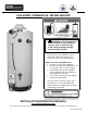
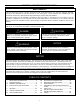

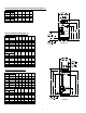


Table Of Contents
- WITH TROUBLESHOOTING GUIDE
- Non-Flue Damper Models (Figure 2)
- Flue Damper Models and Non-Flue Damper Models (Figure 3)
- Non-Flue Damper Models (Figure 4)
- Front, sides and Rear “A”
- Input
- 2 in. (5.1 CM)
- Less than or equal to 300,000 BTUH
- 6 in (15.2 CM)
- Greater than 300,000 BTUH
- IMPORTANT-The flow of combustion and ventilating air must not be obstructed.
- MECHANICAL EXHAUSTING OF ROOM AIR - Where an exhaust fan is installed in the same room with this water heater and combustion air is drawn from inside the room, sufficient openings for air must be provided in the walls. UNDERSIZED OPENINGS WILL CAUSE A...

7
Non-Flue Damper Models (Figure 5)
Flue Damper Models (Figure 5)
The following notes apply to the tables accompanying Figures 1 - 5.
1. All models with flue dampers and/or above 400,000 BTU per hour input employ a “spark to pilot” (IID) ignition system
and requires 120 volt AC electric supply.
2. Model number may have a suffix “N” for natural gas or “X” for liquefied petroleum (LP) gases. Some models may have
“A” as a suffix for ASME. Check the rating plate on front of the water heater for model number verification.
Model Description
A
(in.)
B
(in.)
C
(in.)
D
(in.)
E
(in.)
Capacity
(GAL)
Input
(BTU/hr)
75
160,000
(155,000
LP)
70.13 67.13 65.00 54.50 6
Model Description
A
(cm)
B
(cm)
C
(cm)
D
(cm)
E
(cm)
Capacity
(Liters)
Input
(kW/hr)
283.9
46.9
(45.4 LP)
178 171 165 138 15.2
Model Description
A
(in.)
B
(in.)
C
(in.)
D
(in.)
E
(in.)
Capacity
(GAL)
Input
(BTU/hr)
75 125,000 72.25 67.13 65.00 54.50 5
75
160,000
(155,000
LP)
72.25 67.13 65.00 54.50 6
Model Description
A
(cm)
B
(cm)
C
(cm)
D
(cm)
E
(cm)
Capacity
(Liters)
Input
(kW/hr)
283.9 36.6 183 171 165 138 12.7
283.9
46.9
(45.4 LP)
184 171 165 138 15.2
Figure 5