
Flexible Vent Kit Installation Manual


2
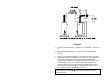
Figure 1
Direct Vent Terminal Clearances
Canadian Installations
1
US Installations
2
A= Clearance above grade, veranda, porch, deck or balcony 12 inches (30.5 cm) 12 inches (30.5 cm)
B= Clearance to widow or door that may be opened 12 inches (30.5 cm) 9 inches (23 cm)
C= Clearance to permanently closed widow *b *b
D=
Vertical clearance to ventilated soffit located above the
terminal within a horizontal distance of 2 feet (61 cm) from
the center line of the terminal
12 inches (30.5 cm)*a
12 inches (30.5
cm)*a
E= Clearance to unventilated soffit 12 inches (30.5 cm) *a
12 inches (30.5 cm)
*a
F= Clearance to outside corner *b *b
G= Clearance to inside corner *b *b
H=
Clearance to each side of center line extended above
meter/regulator assembly
3 feet (.9 m) within a height
15 feet (4.6 m) above the
meter/regulator assembly
*b
I= Clearance to service regulator vent outlet or oil tank vent 36 inches (91 cm) *b
J=
Clearance to non-mechanical air supply inlet to building or
the combustion air inlet to any other appliance
12 inches (30.5 cm) 9 inches (22.8 cm)
K= Clearance to a mechanical air supply inlet 6 feet (1.8 m)
3 feet (.9 m) above if
within 10 feet
horizontally
L=
Clearance above paved sidewalk or paved driveway
located on public property
7 feet (2.1 m)† *b
M= Clearance under a veranda, porch, deck, or balcony 12 inches (30.5 cm)‡ *b
1
In accordance with the current CAN/CGA-B149 Installation Codes.
2
In accordance with the current ANSI Z223.1-(Latest edition)/NFPA 54 National Fuel Gas Code.
† A vent shall not terminate directly above a sidewalk or paved driveway that is located between two single-
family dwellings and serves both dwellings.
‡ Permitted only if a veranda, porch, deck or balcony is fully open on a minimum of two sides beneath the
floor.
*a) A minimum clearance value determined by testing in accordance with section 2.20.
*b) “Clearance in accordance with local installation codes and the requirements of the gas supplier”.