COMMERCIAL ELECTRIC WATER HEATER La estas instrucciones se puede A version Spanishespanola languagede version of these instructions is obtener availablealbyescribirle acontacting la fábrica cuyo nombre aparece la placa especificaciones. the company listed oninthe ratingde plate. ALa Spanish of instrucciones these instructions is available versiónlanguage espãnolaversion de estas se puede obtenerbyal contacting manufacturer listed on the rating escribirle athe la fábrica cuyo nombre aparece en laplate.
TABLE OF CONTENTS General Information ................................................... 3 Installation ............................................................... 4 Locating the Water Heater .............................................. Water Connections ........................................................ Electrical Connections .................................................... Amperage Chart ............................................................ GPH Recovery Capacities .................
GENERAL INFORMATION This electric w ater heater’ s design is certified by Intertek (ETL) and listed in accordance w ith UL1453. CETL listed in accordance w ith Canadian National Standard C22.2, No. 110 -M90. This w ater heater must be installed in accordance w ith local codes. In the absence of local codes, install this w ater heater in accordance w ith the N.E.C. Reference Book (latest edition).
General Information continued- w hile protecting the tank. Additionally, the w ater heater should be flushed w ith appropriate dissolvers to eliminate any bacteria. IMPORTANT Before proceeding, please inspect the w ater heater and its components for possible damage. DO NOT install any damaged components. If damage is evident, please contact the supplier w here the w ater heater w as purchased or the manufacturer listed on the rating plate for replacement parts.
Locating The Water Heater continued- Water heater corrosion and component failure can be caused by the heating and breakdow n of airborne chemical vapors. Examples of some typical compounds that are potentially corrosive are: spray can propellants, cleaning solvents, refrigerator and air conditioning refrigerants, sw imming pool chemicals, calcium or sodium chloride, w axes and process chemicals.
Water Connections NOTE: BEFORE PROCEEDING WITH THE INSTALLATION, CLOSE THE MAIN WATER SUPPLY VALVE. After shutting the main w ater supply valve, open a faucet to relieve the w ater line pressure to prevent any w ater from leaking out of the pipes w hile making the w ater connections to the w ater heater. After the pressure has been relieved, close the faucet. The cold w ater inlet line connects to the inlet nipple at the base of the w ater heater.
Water Connections continued- WARNING For protection against excessive temperatures and pressure, inst all temperature and pressure protective equipment required by local codes, but not less than a combination temperature and pressure relief valve certified by a nationally recognized testing laboratory that maintains periodic inspection of production of listed equipment or materials, as meeting the Requirements for Relief Valves and Automatic Gas Shutoff Devices for Hot Water Supply Systems, ANSI Z21.
Water Connections continued- WARNING Hydrogen gas can be produced in a hot water system served by this water heater that has not been used for a long period of time (generally two weeks or more). Hydrogen gas is extremely flammable. To reduce the risk of injury under these conditions, it is recommended that the hot water faucet be opened for several minutes at the kitchen sink before using any electrical appliance connected to the hot water system.
Water Connections continuedWater temperature over 125°F can cause severe burns instantly or death from scalds. Children, disabled and elderly are at highest risk of being scalded. Review this instruction manual before setting temperature at water heater. Feel water before bathing or showering. Temperature limiting valves are available.
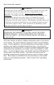
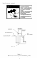
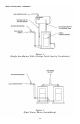
Water Connections continued- Figure 2 (Single Installation With Storage Tank Gravity Circulation) Figure 3 (Dual Water Heater Installation) 10
Electrical Connections Before any electrical connections are made, be sure that the w ater heater is full of w ater and that the manual shut -off valve in the cold w ater supply line is open. If the heating elements are not completely immersed in w ater at all times, they w ill be damaged (burned-out) if energized for even a short period of time. The w arranty does not cover burned-out heating elements. Check the rating plate and w iring diagram before proceeding.
Electrical Connections continued- Amperage Chart kW 208V 240V 277V 380V 415V 480V Input 1Ø 3Ø 1Ø 3Ø 1Ø 3Ø 3Ø 1Ø 3Ø 6 29 17 25 14 22 9 8 12 7 9 43 25 38 22 32 14 13 19 11 12 58 33 50 29 43 19 17 25 14 13.
GENERAL OPERATION Before closing the sw itch to allow electric current to flow to the w ater heater, make certain that the w ater heater is full of w ater and that the cold w ater inlet valve is open. Complete failure of the heating elements w ill result if they are not totally immersed in w ater at all times. When the sw itch is closed, the operation of this electric w ater heater is automatic. The thermostat (s) are preset to provide a w ater temperature of approximately 140° F (60° C) or below .
Thermostat Adjustment There are tw o types of thermostats this electric w ater heater may come equipped w ith from the factory. One type, surface mounted thermostats, directly contacts the w ater heater tank surfac e (see Figure 4). The second type, immersed type are immersed w ithin the w ater heater tank and uses contactor type relays. Before any w ork is done on the w ater heater, disconnect all pow er to the w ater heater by opening the sw itch at the main electrical circuit breaker or fuse box.
Thermostat Adjustment continued- APPROXIMATE TIME/TEMPERATURE RELATIONSHIPS IN SCALDS 120°F (49°C) More than 5 minutes 125°F (52°C) 1½ to 2 minutes 130°F (54°C) About 30 seconds 135°F (57°C) About 10 seconds 140°F (60°C) Less than 5 seconds 145°F (63°C) Less than 3 seconds 150°F (66°C) About 1½ seconds 155°F (68°C) About 1 second Figure 4 Figure 5 15
MAINTENANCE IMPORTANT The w ater heater should be inspected at a minimum of annually by a qualified service technician for damaged components. DO NOT operate this w ater heater if any part is found damaged. Shut off the electric pow er w henever the w ater supply to the w ater heater is off. Shut off the electric pow er and w ater supply, drain the heater completely to prevent freezing w henever the building is left unoccupied during the cold w eather months.
Maintenance continued- 3. At least once a year, check the combination temperature and pressure relief valve to insure that the valve has not become encrusted w ith lime. Lift the lever at the top of the temperaturepressure relief valve several times until the valve seats properly w ithout leaking and operates freely. WARNING When lifting lever of temperature-pressure relief valve, hot w ater w ill be released under pressure.
Maintenance continued- Contact your local plumbing supplier or plumbing professional for replacement parts or contact the company at the address displayed on the rating plate of the w ater heater. For faster and better service, please provide the part name, model, and serial number(s) of the w ater heater(s) w hen ordering parts. READ THE WARRANTY FOR A FULL EXPLANATION OF THE LENGTH OF TIME THAT PARTS AND THE WATER HEATER ARE WARRANTED. Manufactured under one or more of the follow ing U.S.
NOTES 19
NOTES 20