(To be performed ONLY by qualified service providers) Commercial Electric Energy Saver: E32-50S E32-80R E32-120R Manual 239-47157-00B Save this manual for future reference
E32 Medium Duty Commercial Electric Water Heaters Page Service Procedure Introduction ………………………………………………………………………. 2 --- Tools……………………………………………………………………………… 2 --- General Information ……………………………………………………………… 3 --- Sequence of Operation …………………………………………………………… 5 --- Field Conversion of kW, Voltage and Phase…………………………………….. 6 --- Troubleshooting …………………………………………………………………. 9 --- Heating Element Testing ……………...................................................................
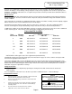
GENERAL INFORMATION Commonly Used Formulas Amps = Watts (for single phase units) Example 4500W/240V = 18.75A Volts Amps = Watts (for balanced 3 phase units) Example 4500W/240V x 1.732 = 10.82A Volts x 1.732 Watts = Amps x Volts Example 18.75A x 240V = 4500W 2 Ohms = Volts 2 Example (240V) / 4500W = 12.
GENERAL INFORMATION Full Load Amperes-(Phase 1/Phase 3) Input Kw 208V 240V 277V 380V 415V 480V 6 28.8/16.6 25/14.4 21.6 10 8.3 12.5/7.2 9 43.2/25 37.5/21.6 32.4 14 12.5 18.7/10.8 12 57.6/33.3 50/28.9 43.3 19 16.7 25/14.4 13.5 64.9/37.5 56.2/32.5 48.7 21 18.8 28.1/16.2 15 72.1/37.5 62.5/36.1 54.1 23 20.9 31.2/18 18 86.5/50 75/43.4 64 28 25 37.5/21.
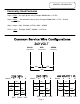
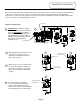
SEQUENCE OF OPERATION E32 series medium duty, field convertible commercial electric water heaters are designed to operate using single phase or three phase service connections. One size fits all Internal fusing is factory installed for all units. When field conversions are required, no fuse change is necessary. Three surface mounted thermostats operating independently are used to control a corresponding heating element. Fuse Block Sequence of Operation.
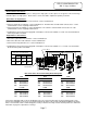
FIELD CONVERSION FOR: KW, Voltage and Phase The E32 series medium duty commercial electric water heaters are field convertible. This allows Qualified Service Providers the ability to convert wattage, voltage and phase using a factory supplied conversion kit as required per the installation. Underwriters Laboratories Inc. recognizes this procedure as herein presented and no deviation from these instructions are allowed.
FIELD CONVERSION FOR: KW, Voltage and Phase Electrical Phase Conversion Electrical phase conversion will require a change from single-phase to three-phase or an opposite conversion change from three-phase to single-phase. Each of these conversions will be explained separately as follows: Three-Phase to Single-Phase 1. Disconnect blue and yellow wires from terminal L-3 of the terminal block 2. Connect yellow wire to terminal L-1 of the terminal block.
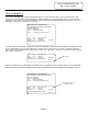
FIELD CONVERSION FOR: KW, Voltage and Phase Rating Plate Modification The heaters rating plate will need to be modified because the conversion altered the electrical characteristics of the heater. Refer to the illustration below that displays a typical commercial electric rating plate that is to be altered. This rating plate is placed on every Commercial Electric water heater produced by Bradford White Corporation. Locate this rating plate on the heater you have just converted.
TROUBLESHOOTING Most common cause for improper electric water heater operation can be linked to heating element failure. When troubleshooting an electric water heater with the incidence of “No Hot Water” or “Insufficient Amount of Hot Water” It is always a good idea to check the heating elements first following the procedure on page 11. Common Heating Element Failures Are: 1. Dry Firing. Element may be partially submerged in water or most likely, completely exposed with no water in tank.
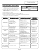
TROUBLESHOOTING Quick Step Plan to Hot Water WARNING High voltage exposure. Use caution when making voltage checks to avoid personal injury. 1. TURN OFF power to water heater and check all wire connections to insure they are tight and corrosion free. 2. Turn power “ON” and determine that line voltage is present (see pg 12), and the high limit (ECO) has not actuated (see pg 13). 3. Check for blown fuse (see pg 13). 4. Check for inoperative heating element (see procedure on page 11). 5.
SERVICE PROCEDURE E32-I Heating Element Testing Testing For Open Or Burned Out Element. WARNING High voltage exposure. Be sure power is turned OFF to water heater prior to performing this procedure. Step 1. TURN OFF POWER TO WATER HEATER. Step 2. Remove thermostat/element access cover(s) from front of water heater. Remove insulation and plastic cover from thermostat. Step 3. Disconnect wires from heating element. Step 4. Set multi-meter to “ohms” setting. Step 5.
SERVICE PROCEDURE E32-II Line Voltage Testing Line Voltage Testing WARNING High voltage exposure. Use caution when making voltage checks to avoid personal injury. 1. Turn “OFF” power to water heater. 2. Open control box located at the top of the heater to allow access to terminal block. 3. Set multi-meter to volts AC. Check voltage across L1 & L2 of terminal block 4. Turn power “ON” to water heater. Single phase Service from panel 5. For 3 phase service, go to step 7. 6.
SERVICE PROCEDURE E32-III Fuse Testing Fuse Testing 1. Turn “OFF” power to water heater. 2. Open control box located at the top of the heater to allow access to fuse block. WARNING High voltage exposure. Be sure power is turned OFF to water heater prior to performing this procedure. 3. Disconnect wire leads from fuse block. NOTE: It may be necessary to label wires for proper re-connection when finished. 4. Set multi-meter to the “Ohms” setting. 5.
SERVICE PROCEDURE E32-IV Thermostat Testing Thermostat Operation Testing WARNING High voltage exposure. Use caution to avoid personal injury during this procedure. Water In Tank Is Cold With Power ON. 1. This procedure assumes line voltage, ECO and elements are in working order. 2. Turn power “ON” to water heater. 3. Set multi-meter to “Volts AC”. 4. Check across terminals L1 & L3 of thermostat (see illustration 8) A) Rated voltage NOT present, Check fuses.
SERVICE PROCEDURE E32-V Thermostat Removal and Replacement Thermostat Removal WARNING High voltage exposure. Be sure power is “OFF” when performing this procedure. 1. Turn power “OFF” To water heater. 2. Remove access cover(s) and insulation. 3. Remove plastic thermostat protector from thermostat(s). 4. Disconnect wires from thermostat terminals. It may be necessary to label wires for proper re-connection to new thermostat. 5. Note thermostat temperature setting for proper setting of new thermostat. 6.
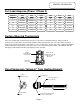
SERVICE PROCEDURE E32-VI Heating Element Removal and Replacement WARNING High voltage exposure. Be sure power is “OFF” when performing this procedure. Heating Element Removal 1. Turn power “OFF” To water heater. 2. Turn off cold water supply to heater. Connect hose to drain spigot of water heater and route to an open drain. Open a nearby hot water faucet to vent heater for draining. Open drain spigot of water heater and allow heater to drain to a point below the Element(s).
SERVICE PROCEDURE E32-VII Dip Tube and Anode Inspection and Replacement Dip Tube Inspection and Replacement WARNING Heater components and stored water may be HOT when performing the following steps in this procedure. Take necessary precaution to prevent personal injury. Step 1. Turn power “OFF” to water heater. Step 2. Turn off cold water supply to heater. Connect hose to drain spigot of water heater and route to an open drain. Open a nearby hot water faucet to vent heater for draining.
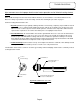
Generic Parts List 1. Hot Water Outlet Anode 2. T&P Relief Valve 3. Cold Water Inlet Dip Tube 4. Control Box 5. Ground Lug 6. Fuse 7. Fuse Block 8. Terminal Block 9. Brass Drain Valve 10. Thermostat Mounting Bracket 11. Element Gasket 12. Heating Element 13. Thermostat Surface Mount 14. Thermostat Protector 15. Thermostat/Element Access Cover 16.
Email parts@bradfordwhite.com techserv@bradfordwhite.com www.bradfordwhite.