SERVICE MANUAL Troubleshooting Guide and Instructions for Service (To be performed ONLY by qualified service providers) Ultra High Efficiency Water Heater with ICON and Integrated Control Systems Models Covered: SECTION 1 (PG. 9): SERIAL NUMBERS “XC-” (MAR. 2021) AND LATER: 60T125(E)*(N,X)(A)(2); 60T150(E)*(N,X)(A)(2); 60T199(E)*(N,X)(A)(2); 100T150(E)*(N,X)(A)(2); 100T199(E)*(N,X)(A)(2); 100T250(E)*(N,X)(A)(2); 100T300(E)*(N,X)(A)(2) SECTION 2 (PG. 53): SERIAL NUMBERS “XL-” (NOV.
Table of Contents Page Service Procedure Serial Number Breakdown……………………………………… 4 --- Introduction……………………………………………………….. 5 --- How to Use this Manual…………………………………………. 5 --- Tools Required for Service……………………………………….. 6 --- Venting Tables and Approved Venting………………………… 7 --- Specifications…………………………………………………….. 9 --- Section 1: Serial Numbers “XC-” (March 2021) and Later 2 ICON System Features…………………………………………. 10 --- Sequence of Operation…………………………………………..
Table of Contents Section 2: Serial Numbers “XL-” (Nov. 2021) and Later with -895 Designator Page Service Procedure Specifications……………………………………………………… 53 …... Features……..…………………………………………………….. 54 --- Sequence of Operation………………………………………….. 55 --- Troubleshooting………………………………………………….. 56 --- Thermostat Circuit Testing and Replacement…………………. 70 I Combustion System Testing and Replacement……………….. 74 II Burner Tube Inspection and Replacement…………………….
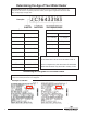
Determining the Age of Your Water Heater SERIAL NUMBER SECTION: The first two characters represent the year and month of manufacture. The remainder of the serial is a sequential production number, seven digits in length before December 2007 (DM), and eight digits in length after.
Introduction The Ultra High Efficiency Water Heater is designed to deliver a high thermal efficiency rating in a quiet running unit with venting options that allow for installation flexibility. Several technologically advanced design features are incorporated in the design that will require additional knowledge on the part of the qualified service provider.
Tools Required for Service Manometer: Two types available, a liquid “U” tube type or a digital (magna-helic) type. This device is used to measure gas and/or air pressures and vacuum. Multi-Meter: A digital type is strongly recommended. This device is used to measure electrical values. The meter you select must have the capability to measure volts AC, volts DC, Amps, micro-amps and ohms. Thermometer: Used to measure water temperature. An accurate thermometer is recommended.
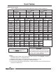
Vent Tables Maximum Vent Length Table 3 - Maximum Vent Length (Combined Maximum Length for Intake and Exhaust) 60T-125 2” Vent Pipe Max. Intake Length Max. Exhaust Length 3” Vent Pipe Max. Intake Length Max. Exhaust Length 4” Vent Pipe Max. Intake Length Max. Exhaust Length Power Direct Vent 15 ft (4.5 m) 15 ft (4.5 m) Power Vent N/A 30 ft (9.2 m) Max. Intake Length Max. Exhaust Length 60T-150 100T-199 Power Power Direct Vent Vent 50 ft N/A (15.2 m) 50 ft 100 ft (15.2 m) (30.
Venting Tables Cont. Example: 100T199 A 3" balanced direct vent system has 30 feet of straight exhaust pipe and 30 feet of straight intake pipe. It has 3- 90° elbows in the exhaust and 3- 90° elbows in the intake. It has 1- 45° elbow in the exhaust and 1- 45° elbow in the intake. Therefore: 6- 90° elbows x 5 feet = 30 feet. 2- 45° elbows x 2½ feet = 5 feet. 60 feet of straight pipe + 30 feet + 5 feet = 95 feet. System is within “Maximum Combined Length” from table above.
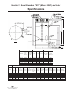
Section 1: Serial Numbers “XC-” (March 2021) and Later Specifications Recovery GPH at Degree Rise Model No. Input Rate BTU/hr 1st Hr. Del Gal @ 100 °F Rise 40°F 100°F 140°F Stg. Capacity US Gal Therm. Efficiency % 60T125 60T150 60T199 100T150 100T199 100T250 100T300 125,000 150,000 199,999 150,000 199,999 250,000 300,000 187 211 265 250 309 364 405 363.6 422.7 557.6 450.5 597 734.8 836.4 145.5 169.1 223 180.2 238.8 293.9 334.5 103.9 120.8 158 129 171 210 239 60 60 60 100 100 100 100 96.
Icon System Features of ICON System Module • Water heater digital display on control board for setting and displaying the temperature setpoint. Pressing temperature UP and DOWN buttons changes the temperature setpoint. Temperature format may be displayed in °F or °C. • Single control board with plug in wiring controls temperature, ignition, and blower operation. • Plug in wiring reduces chance of miswiring.
Sequence of Operation 1. Thermostat calls for heat. 2. Combustion blower starts at a reduced rpm for a “soft” start light off. 3. Blower pre-purge period of approximately 15 seconds. 4. Ignition control board runs an internal verification safety check for approximately 15 seconds. 5. Trial for ignition (approximately 5 seconds per trial, 3 trials total): a. Spark establishing period (3 seconds), gas valve opens, sparks from spark rod to ground rod, igniting the fuel air mixture at the burner surface. b.
Sequence of Operation Lockout Conditions The system will go into lock out mode for the following reasons: 1. ERROR CODE 110 a. Control board will go into soft lockout if the main burner cannot be lit or fails to prove flame after 3 ignition trials. The water heater digital display indicates a lockout condition by showing error code 110 with “Service Needed” on the control board’s digital display. Refer to error codes in the diagnostic section of this Service Manual.
Building Management System (BMS) All water heaters with ICON Systems can be equipped with a gateway kit that will facilitate a Building Management System (BMS) connection to Modbus or Bacnet®. This kit is sold separately and is not factory installed. A full installation, operation, and troubleshooting manual is provided with the gateway kit. CAUTION Before beginning any Troubleshooting operations listed below, please note that the gateway kit and BMS may need to be disconnected from the heater.
BMS Wiring Diagram NOTICE The Building Management System (BMS) is only compatible with units that have ICON controllers.
Troubleshooting System Observation WARNING Water Heater Fault: Water heater does NOT operate. Display Error Code: Water heater digital display does NOT operate - blank display. 120 volt potential exposure. Use caution making voltage checks to avoid personal injury. Check main power supply to water heater. Check fuse, circuit breaker, plug receptacle, line cord, and wiring to water heater. CAUTION Use caution to NOT damage connectors when making voltage measurements or jumping terminals.
Troubleshooting CAUTION WARNING Use caution to NOT damage connectors when making voltage measurements or jumping terminals. Continued from previous page. Y Does combustion blower operate? Error code 62 on display. Measure voltage between black and white wires, of the 3 wire harness, at the blower (make sure the digital display shows “heating” in the status mode, if not increase the setpoint). Is there 110-120 VAC? N N Y Verify 120V from power switch.
Display Control Water Heater Display and Control Buttons To Increase Temperature Setpoint Step 1. Press and hold “Temperature Up” button until desired setpoint temperature appears on the display. Step 2. Press “DONE” button for new setting to take effect immediately. If the “DONE” button is not pressed, the new temperature setting will take effect in approximately 10 seconds.
To Decrease Temperature Setpoint Step 1. Press and hold “Temperature Down” button until desired setpoint temperature appears on the display. Step 2. Press “DONE” button for new setting to take effect immediately. If the “DONE” button is not pressed, the new temperature setting will take effect in approximately 10 seconds. To View Combustion Rate Step 1. Select Next while viewing DHW Setpoint in User Mode to access Rate screen. Rate will only be displayed while the burner is operating. Step 2.
To Change Temperature Format in Display from F to C or ˚C to ˚F Step 1. Enter “Set-Up Mode” by pressing both UP/DOWN buttons together for 3 seconds. Step 2. Use the arrows to select between °F and °C Step 3. Press done to return to main screen or timeout/change will occur in one minute. An energy cut out (ECO) is incorporated in the sensor and control board which will shut off all gas supply to the burner if the water heater temperature exceeds 207°F (93°C).
Troubleshooting Accessing Diagnostic Mode on the Water Heater Display (FOR SERVICE PERSONNEL ONLY) The display has a Diagnostic Mode to access information in aiding servicing of the water heater. This procedure is for service and installation personnel only. To enter the Diagnostic Mode, follow the steps illustrated below: WARNING The following procedure is for service and installation personnel ONLY. Resetting lockout conditions without correcting the malfunction can result in a hazardous condition.
Step 3. Press the lower right “Next” button. The display will flash and show the number of any alert codes. These are not currently used. Step 4. Press lower right “Next” button. The display will flash and show the number of any Lockout codes. If there are no lockouts, the display will show 00. If there are multiple lockout codes “Next” will scroll through them. Step 5. Press “Next”, the display will show “DHW MAX”.
Step 6. Press Next, display will show “DELTA T DHW”, this is the real time temperature reading of the tank. Step 7. Press “Done” to exit Diagnostic Mode and return to the DHW setpoint in User Mode.
DIAGNOSTIC ERROR CODES AND TROUBLESHOOTING PROCEDURES FOR EF MODELS WITH ICON SYSTEMS CONTROL NOTICE The ICON control system can produce soft and hard lockouts. Soft lockouts are displayed if active and are not stored in Diagnostic Mode history. The control will periodically attempt to resume normal operation when in soft lockout conditions. If the system resumes normal operation a soft lockout will clear instantly; hard lockouts will display if active and require manual reset.
Error Code Definition of Code Cause of Problem and Actions Taken to Correct • Check the wiring from the water temperature sensor to the control module. Measure the resistance of each outside wire to the center wire. Measure the tank temperature and compare with the chart below. If either outside wire has a much different resistance reading, replace the sensor. Make sure the sensor is securely held inside the well with the clip. If the problem persists and the sensor and wiring check O.K.
Error Code Definition of Code 172 Water temperature sensor resistance invalid NOTE Cause of Problem and Actions Taken to Correct • • Hold 93 will be displayed if this value remains out of range Measure the resistance of the water temperature sensor and compare it with the tank temperature using the chart below (Reference Appendix A Sensor Resistance at Various Temperatures on pg. 29).
Service Procedure I Thermostat Circuit Testing and Replacement IMPORTANT NOTE: This procedure assumes a cool tank. Condition: Water heater not operating. Digital display shows error code 93 (sensor reading faulty). WARNING 120 volt potential exposure. Use caution making voltage checks to avoid personal injury. CAUTION Use caution to NOT damage connectors when making voltage measurements or jumping terminals. Unplug or disconnect electrical power to the water heater.
Service Procedure I Thermostat Circuit Testing and Replacement (Continued) Continued from previous page. WARNING DO NOT operate the water heater without verifying that the overheating condition has been corrected. Condition: Water heater not operating. Digital display shows error code 80 high water temperature (over 207°F) (continued from previous page). Once cause of overheating condition has been diagnosed and corrected, the control board may be reset.
Service Procedure I Thermostat Circuit Testing and Replacement (Continued) Thermostat Sensor (Thermistor) Replacement Procedure WARNING 1. Position main power switch to “OFF.” 2. Disconnect (unplug) water heater from 120 volt power source. 3. Unlatch and remove top surround cover from top of the water heater. 120 volt potential exposure. Use caution making voltage checks to avoid personal injury. 4. Fold back insulation by top outlet location to expose temperature sensor. 5.
Service Procedure I Thermostat Circuit Testing and Replacement (Continued) Appendix – A Sensor Resistance at Various Temperatures Be careful when making voltage measurements or jumping terminals NOT to damage or deform connectors or connector pins. Draw water from the Temperature and Pressure Relief Valve. Compare the Temperature with Temperature Ohms Chart below. Example: If temperature of the sensor is 84 °F, then the resistance through the sensor would be 8449 (see shaded area).
Service Procedure I Thermostat Circuit Testing and Replacement (Continued) Thermostat Sensor (Thermister) Replacement Procedure 1. Position main power switch to OFF. WARNING 120 volt potential exposure. Isolate the appliance and reconfirm power is disconnected using a multi-meter. 2. Disconnect (unplug) the water heater from 120 volt power source. 3. Unlatch and remove the top of the surround cover from the top of the water heater. Sensor shown fully inserted into well 4.
Service Procedure II Combustion System Testing and Replacement Observe burner operation through the sight glass located on the combustion insert mounting flange. Normal burner operation should ignite smoothly, without evidence of coughing or huffing upon ignition. The burner flame should be a blue flame near the burner surface in a uniform flame pattern. Occasional yellow or white streaks are normal. WARNING 120 volt potential exposure. Use caution making voltage checks to avoid personal injury.
Service Procedure II Combustion System Testing and Replacement (Continued) Observe burner operation through the sight glass located on the combustion insert mounting flange. Normal burner operation should ignite smoothly, without evidence of coughing or huffing upon ignition. The burner flame should be a blue flame near the burner surface in a uniform flame pattern. Occasional yellow or white streaks are normal. WARNING 120 volt potential exposure.
Service Procedure II Combustion System Testing and Replacement (Continued) Combustion System Removal Procedure 1. Position main power switch to OFF. 2. Disconnect (unplug) water heater from 120 volt power source. 3. Turn OFF gas supply to the water heater. 4. Unlatch and remove the surround cover from the top of the water heater. WARNING 120 volt potential exposure. Isolate the appliance and reconfirm power is disconnected using a multi-meter.
Service Procedure II Combustion System Testing and Replacement (Continued) Combustion System Removal Procedure 1. Fully inspect burner mounting insert gasket for the following: a) Tears d) Dirt or debris b) Missing material e) Other imperfections that would inhibit proper seal c) Cracks If gasket is NOT affected by any of the above, gasket replacement is not required. 2. Install combustion assembly using new gasket or fully inspected gasket from step 1.
Service Procedure III Burner Tube Inspection and Replacement WARNING Burner Tube Removal Procedure 120 volt potential exposure. Isolate the appliance and reconfirm power is disconnected using a multi-meter. 1. Position main power switch to OFF. 2. Disconnect (unplug) water heater from 120 volt power source. WARNING Heater components may be HOT when performing the following steps in this procedure. Take necessary precaution to prevent personal injury. 3. Turn OFF gas supply to the water heater. 4.
Service Procedure III Burner Tube Inspection and Replacement (Continued) WARNING Burner Tube Inspection Heater components may be HOT when performing the following steps in this procedure. Take necessary precaution to prevent personal injury. 1. Inspect burner tube as follows (ceramic fiber mesh burner, water heaters prior to serial number “CK”): a) Visually inspect ceramic fiber mesh; mesh should be uniform in appearance without large gaps, tears, or fraying.
Service Procedure IV Gas Valve Replacement Gas Valve Replacement Procedure WARNING 120 volt potential exposure. Isolate the appliance and reconfirm power is disconnected using a multi-meter. 1. Position main power switch to OFF. 2. Disconnect (unplug) water heater from 120 volt power source. 3. Turn OFF gas supply to water heater. 4. Unlatch and remove the surround cover from the top of the water heater. 5.
Service Procedure V Blower Testing and Replacement Does blower energize? Ensure digital display shows “Heating.” Raise temperature setpoint if necessary. Are collector high limit switch and pressure switches in normally closed position? Y N N Is there 120VAC across the white and black wires at the incoming power harness connection? (see image to right). Call Technical Support. Y Y Refer to ignition control board illustration below.
Service Procedure V Blower Testing and Replacement (Continued) Blower Replacement Procedure 1. Position main power switch to OFF. WARNING 120 volt potential exposure. Isolate the appliance and reconfirm power is disconnected using a multi-meter. 2. Disconnect (unplug) water heater from 120 volt power source. 3. Turn OFF gas supply to water heater. 4. Unlatch and remove surround cover from top of heater. 5. Disconnect wire harness from blower. 6.
Service Procedure VI Exhaust Pressure Switch Testing and Replacement Exhaust Pressure Switch Replacement Procedure 1. Position main power switch to OFF. 2. Loosen adhesive backed rubber escutcheon from service panel access cover and slide escutcheon back along exhaust pipe to allow for removal of cover. 3. Remove screws from service panel access cover (¼" nut Rubber escutcheon driver) and remove cover from heater (see images at right). 4.
Service Procedure VI Blocked Vent Pressure Switch Testing and Replacement (Continued) WARNING WARNING 120 volt potential exposure. Use caution making voltage checks to avoid personal injury. Make sure exhaust collector compartment is not overheating (350°F) before resetting vent safety switch. If there is evidence the collector compartment is overheating, call Technical Support. Sequence of Operation: The blocked vent pressure switch monitors the pressure in the exhaust tube.
Service Procedure VI Blocked Vent Pressure Switch Testing and Replacement (Continued) Check Exhaust Tube Pressure With manometer, take a reading at the exhaust tube pressure tap location. Is value negative (-) or slightly positive (see image below). N Is exhaust venting system blocked or obstructed? Check condensate elbow and drain. Y Clear obstruction. Determine cause and correct.
Service Procedure VI Blocked Vent Pressure Switch Testing and Replacement (Continued) Exhaust Pressure Switch Replacement Procedure 1. Position main power switch to “OFF” position. 2. Loosen adhesive backed rubber escutcheon from service panel access cover and slide escutcheon back along exhaust pipe to allow for removal of cover. Rubber escutcheon 3. Remove screws from service panel access cover (¼" nut driver) and remove cover from heater (see images at right). 4.
Service Procedure VII Flame Sensor Testing and Replacement Flame Sensor Testing Procedure Refer to image below. Is there a minimum of 1 µA during 2 second flame proving period? (may be checked on digital display). Y N With flame sensor disconnected from ignition control board, check continuity to ground. Is there continuity to ground? Refer to ignition control board illustration. (24-28 volts should maintain beyond the 2 second flame proving period.
Service Procedure VIII Spark Rod Gap Adjustment and Replacement WARNING Spark Rod Gap Inspection and Adjustment 1. Remove combustion system as described in Combustion System Removal Procedure (pg 33). 2. Measure spark gap between the spark rod and burner tube. Acceptable spark gap is between 3/16”-1/4” (see images below). Spark gap must be set to 3/16” to 1/4”. Failure to set and verify proper spark gap may result in a delayed ignition resulting in damage to the water heater.
Service Procedure VIII Spark Rod Gap Adjustment and Replacement (Continued) WARNING Spark Rod Replacement Procedure 120 volt potential exposure. Isolate the appliance and reconfirm power is disconnected using a multimeter. 1. Position main power switch to OFF. CAUTION 2. Disconnect (unplug) water heater from 120 volt power source. If spark rod is replaced for any reason, the combustion system MUST be removed and the spark gap to the burner measured and adjusted properly. 3.
Service Procedure IX Ignition Module/Control Board Replacement Control Board Replacement WARNING 1. Position main power switch to OFF. 2. Disconnect (unplug) water heater from 120 volt power source. 120 volt potential exposure. Isolate the appliance and reconfirm power is disconnected using a multimeter. 3. Unlatch and remove top surround cover from top of water heater. 4. Locate the control board. 5. Carefully disconnect all wire connections from the control board.
Service Procedure X Transformer Replacement Transformer Replacement Procedure WARNING 1. Position main power switch to OFF. 120 volt potential exposure. Isolate the appliance and reconfirm power is disconnected using a multimeter. 2. Disconnect (unplug) water heater from 120 volt power source. 3. Unlatch and remove surround cover from top of water heater. 4.
Service Procedure XI Vent Safety Switch Testing and Replacement WARNING WARNING Make sure the exhaust collector compartment is not overheating (350°F) before resetting vent safety switch. If there is evidence the collector compartment is overheating, call Technical Support. 120 volt potential exposure. Isolate the appliance and reconfirm power is disconnected using a multimeter. Sequence of Operation Error code 67 will display indicating an open circuit for the vent safety switch.
Service Procedure XI Vent Safety Switch Testing and Replacement (Continued) WARNING Vent Safety Switch Replacement Procedure 1. Position main power switch to OFF. 120 volt potential exposure. Isolate the appliance and reconfirm power is disconnected using a multimeter. 2. Loosen the adhesive backed rubber escutcheon from the service panel access cover and slide the escutcheon back along the exhaust pipe to allow for removal of cover (see photos below). 3.
Service Procedure XII Flue Baffle Inspection and Replacement WARNING Heater components may be HOT when performing the following steps in this procedure. Take necessary precaution to prevent personal injury. Flue Baffle Inspection and Replacement 1. Disassemble heater per Disassembly Procedure for Access to Anodes and Flue Baffles. 2. Remove flue baffles from heater using pliers (8 two inch (2”) baffles & 2 four inch (4”) baffles). 3. Visually inspect flue baffles.
Service Procedure XIII Powered Anode Replacement WARNING! Water heater components may be HOT when performing the following steps in this procedure. Take necessary precaution to prevent personal injury. The powered anode control module is located on the vertical side of the control panel inside the surround panel. The control has a LED indicator light to show the status of operation.
Section 2: Serial Numbers “XL-” (Nov. 2021) and Later with -895 Designator Specifications Recovery GPH at Degree Rise Model No. Input Rate BTU/hr 1st Hr. Del Gal @ 100 °F Rise 40°F 100°F 140°F Stg. Capacity US Gal Therm. Efficiency % 60T125 60T150 60T199 100T150 100T199 125,000 150,000 199,999 150,000 199,999 187 211 265 250 309 363.6 422.7 557.6 450.5 597 145.5 169.1 223 180.2 238.8 103.9 120.8 158 129 171 60 60 60 100 100 96.0 93.0 92.0 97.0 97.0 DIMENSIONS (INCHES) Model No.
Integrated Control System Serial numbers XL- (November 2021) and after with -895 designator Features of Integrated Control System • Attractive digital water heater display on control panel for setting and displaying the temperature setpoint. Pressing temperature UP and DOWN buttons changes the temperature setpoint. The same water heater display is used on all models. Temperature setpoint may be displayed in °F or °C.
Sequence of Operation 1. Thermostat calls for heat. 2. Combustion blower starts. 3. Blower pre-purge period of 30 seconds. 4. Trial for Ignition (5 seconds, 3 trials). a. Flame establishing period (3 seconds), gas valve opens, sparks from spark rod to burner surface to ignite the gas. b. Burner on, flame proving period (2 seconds). Requires a minimum of 0.8 microamp through flame sense rod to prove flame. c.
Troubleshooting WARNING Water Heater Fault: Water heater does not operate. Display Error Code: Water heater does not operate – blank display. 120 volt potential exposure. Use caution making voltage checks to avoid personal injury. CAUTION Check main power supply to water heater – fuse, circuit breaker, plug receptacle, line cord, or wiring to water heater. Check to make sure switch on front of control panel is in the ON position. Refer to control board illustration.
Troubleshooting WARNING From previous page. 120 volt potential exposure. Use caution making voltage checks to avoid personal injury. CAUTION Does the combustion blower operate? Use caution to not damage connectors when making voltage measurements or jumping terminals. N Y Error code #29 on display. Refer to control board illustration. Measure voltage between terminals P7(3) & P7(5) on the “inducer” output (make sure the control display shows “heating” in the status mode.
Troubleshooting Accessing Service Mode on Control Display (FOR SERVICE PERSONNEL ONLY) The display has a “service mode” for changing the maximum setpoint and accessing information in aiding servicing of the water heater. This procedure is for service and installation personnel only. To enter the Service Mode, follow the steps illustrated below: Step 1: Press Select and Temperature Up buttons together and hold for 3 seconds until “Max Setpoint” is shown in the display.
Sequence of Modes continued- 1. Max Setpoint (Display/Change) 2. Tank Sensor Temperature, Displayed Water Temperature Average 3. Flame Current of Burner Flame Sensor (Displays only in the Heating Cycle) 4.
Sequence of Modes continued- 5. °F/°C (Display/Change) 6. Differential (Display only – shows the differential of the thermostat) 7. Software Version (Display only) 8. Error Code History (Displays if there are present error codes or up to 10 previous error codes). Water heater display will show a “--” if there are no error codes.
To change the Maximum Setpoint Limit (Max Setpoint) for the temperature setpoint: Step 1: In Service Mode press the Select button until Max Setpoint is displayed. WARNING! Setting the water temperature to the maximum setpoint can result in scalding hot water delivered to the faucets. It is highly recommended that the maximum setpoint be adjusted to the lowest temperature possible for the needs of the installation.
Max Setpoint Limit continued- Step 5: 30 seconds after the last button press, the water heater display will go back to User Mode. It will read “Max Setpoint” without showing a temperature value if the temperature setpoint is at the maximum setting. The water heater display can be set back to the User Mode immediately by pressing both the Temperature Up and Select buttons together for 3 seconds.
To Display and Change Temperature Setpoint: Step 1: In Service Mode, press the Select button until “Setpoint” is shown in the water heater display. Step 2: Press the Set button to enter the setting mode. “Setpoint” will flash in the water heater display. Step 3: To raise the temperature setpoint, press the Temperature Up button until the desired temperature is shown in the water heater display.
Change Temperature Setpoint continued- Step 4: To lower the temperature setpoint, press the “Temperature Down” button until the desired temperature is shown on the water heater display. Step 5: When the desired setpoint is reached on the water heater display, press the Set button to confirm the new setpoint. “Setpoint” stops flashing in the water heater display.
Change Temperature Format in Display continued- Step 3a: Press the Temperature Up button to change temperature format to °C. Step 3b: Press the Temperature Up button to change temperature format to °F. Step 4: Press the Set button to confirm °F or °C format. “°F/°C” will stop flashing in the water heater display. Step 5: Pressing the Select button will return the display to setpoint in format selected (°F or °C) immediately.
Error Codes and Error History Display: If there is an operating problem with the water heater, an error code number will appear on the water heater display with “Service Needed” to the right of the “Status” indicator. The error code label is located under the Water Heater Display and the following section in this Service Manual explains the error codes with corrective actions to repair the water heater.
View Previous Error Code continued- Step 3: Press the Select button to view the error code for code 10. If there is a number displayed, note what the number is. The label next to the water heater display will identify the code number. If no number is displayed with only a “--“ in the water heater display, then there has not been an error code for error code index 10. Step 4: Press the Temperature Down button to change the previous code index, code 9.
View Previous Error Code continued- Step 7: 10 seconds after the last button press, the Water Heater Display will revert back to the current error code display. To exit Service Mode, either wait 30 seconds or press Temperature Up button and Select button for 3 seconds. Error Code Definitions If the water heater has an operating problem, there will be a number in the water heater display with “Service Needed” shown below the error code number. Note the error code and the definition in the chart below.
Troubleshooting Resetting Error Codes WARNING The following procedure is for service and installation personnel ONLY. Resetting lockout conditions without correcting the malfunction can result in a hazardous condition. If an error code is displayed (except for 4, low flame sense current), the water heater will be in a Lockout Condition with the water heater display showing the error code number and “Service Needed” in the status section of the display window.
Service Procedure I Thermostat Circuit Testing and Replacement WARNING 120 volt potential exposure. Use caution making voltage checks to avoid personal injury. NOTE: This procedure assumes a cool tank. CAUTION Use caution to not damage connectors when making voltage measurements or jumping terminals. Condition: Water heater not operating. Display shows error code 32 (Sensor Reading Faulty) Unplug or disconnect electrical power to the water heater. Check continuity of wire harness to sensor.
Service Procedure I Thermostat Circuit Testing and Replacement (Continued) WARNING DO NOT operate the water heater without verifying that the overheating condition has been corrected. Continued from previous page. Condition: Water heater not operating. Display shows error code 65 (high water temperature, over 200 °F). Once cause of overheating condition has been diagnosed and corrected, the control may be reset. • • • • • • Reconnect and switch ON power to the water heater.
Service Procedure I Thermostat Circuit Testing and Replacement (Continued) Appendix – A Sensor Resistance at Various Temperatures Be careful when making voltage measurements or jumping terminals NOT to damage or deform connectors or connector pins. Draw water from the Temperature and Pressure Relief Valve. Compare the Temperature with Temperature Ohms Chart below. Example: If temperature of the sensor is 84 °F, then the resistance through the sensor would be 8449 (see shaded area).
Service Procedure I Thermostat Circuit Testing and Replacement (Continued) Thermostat Sensor (Thermister) Replacement Procedure WARNING 120 volt potential exposure. Isolate the appliance and reconfirm power is disconnected using a multi-meter. 1. Position main power switch to OFF. 2. Disconnect (unplug) the water heater from 120 volt power source. 3. Unlatch and remove the top of the surround cover from the top of the water heater. 4.
Service Procedure II Combustion System Testing and Replacement Observe burner operation through the sight glass located on the combustion insert mounting flange. Normal burner operation should ignite smoothly, without evidence of coughing or huffing upon ignition. The burner flame should be a blue flame near the burner surface in a uniform flame pattern. Occasional yellow or white streaks are normal. WARNING 120 volt potential exposure. Use caution making voltage checks to avoid personal injury.
Service Procedure II Combustion System Testing and Replacement (Continued) Observe burner operation through the sight glass located on the combustion insert mounting flange. Normal burner operation should ignite smoothly, without evidence of coughing or huffing upon ignition. The burner flame should be a blue flame near the burner surface in a uniform flame pattern. Occasional yellow or white streaks are normal. WARNING 120 volt potential exposure.
Service Procedure II Combustion System Testing and Replacement (Continued) Combustion System Removal Procedure WARNING 120 volt potential exposure. Isolate the appliance and reconfirm power is disconnected using a multi-meter. 1. Position main power switch to OFF. 2. Disconnect (unplug) water heater from WARNING 120 volt power source. Heater components may be HOT when performing the 3. Turn OFF gas supply to the water heater. following steps in this procedure. Take necessary 4.
Service Procedure II Combustion System Testing and Replacement (Continued) Combustion System Removal Procedure 1. Fully inspect burner mounting insert gasket for the following: a) Tears d) Dirt or debris b) Missing material e) Other imperfections that would inhibit proper seal c) Cracks If gasket is NOT affected by any of the above, gasket replacement is not required. 2. Install combustion assembly using new gasket or fully inspected gasket from step 1.
Service Procedure III Burner Tube Inspection and Replacement WARNING 120 volt potential exposure. Isolate the appliance and reconfirm power is disconnected using a multi-meter. Burner Tube Removal Procedure 1. Position main power switch to OFF. WARNING 2. Disconnect (unplug) water heater from 120 volt Heater components may be HOT when performing power source. the following steps in this procedure. Take necessary 3. Turn OFF gas supply to the water heater. precaution to prevent personal injury. 4.
Service Procedure III Burner Tube Inspection and Replacement (Continued) WARNING Heater components may be HOT when performing the following steps in this procedure. Take necessary precaution to prevent personal injury. 1. Inspect burner tube as follows: a) Outer fiber mesh should be uniform with no tears or deterioration. 2. If burner tube is affected by any of the above, replacement is required. Refer to burner tube replacement procedure below.
Service Procedure IV Gas Valve Replacement Gas Valve Replacement Procedure WARNING 120 volt potential exposure. Isolate the appliance and reconfirm power is disconnected using a multi-meter. 1. Position main power switch to OFF. 2. Disconnect (unplug) water heater from 120 volt power source. 3. Turn OFF gas supply to water heater. 4. Unlatch and remove the surround cover from the top of the water heater. 5.
Service Procedure V Blower Testing and Replacement Does blower energize? (Ensure control display shows “Heating”; raise temperature setpoint if necessary). Y Is there 120 VAC across the white and black wires at the terminal block? (see images) Y Is there 120VAC between P7(5) and P7(3)? N N Is there 120 VAC across the white and black wires at the terminal block? (see images) Y Refer to ignition module/control board illustration.
Service Procedure V Blower Testing and Replacement (Continued) WARNING Blower Replacement Procedure 120 volt potential exposure. Isolate the appliance and reconfirm power is disconnected using a multi-meter. 1. Position main power switch to OFF. 2. Disconnect (unplug) water heater from 120 volt power source. 3. Turn OFF gas supply to water heater. 4. Unlatch and remove surround cover from top of heater. 5. Disconnect wire harness from blower. 6.
Service Procedure VI Blocked Vent Pressure Switch Testing and Replacement WARNING WARNING 120 volt potential exposure. Use caution making voltage checks to avoid personal injury. Make sure exhaust collector compartment is not overheating (350°F) before resetting vent safety switch. If there is evidence the collector compartment is overheating, call Technical Support. Sequence of Operation: The blocked vent pressure switch monitors the pressure in the exhaust tube.
Service Procedure VI Blocked Vent Pressure Switch Testing and Replacement (Continued) Check Exhaust Tube Pressure With manometer, take a reading at the exhaust tube pressure tap location. Is value negative (-) or slightly positive (see image below). N Is exhaust venting system blocked or obstructed? Check condensate elbow and drain. Y Clear obstruction. Determine cause and correct.
Service Procedure VI Blocked Vent Pressure Switch Testing and Replacement (Continued) Exhaust Pressure Switch Replacement Procedure 1. Position main power switch to “OFF” position. 2. Loosen adhesive backed rubber escutcheon from service panel access cover and slide escutcheon back along exhaust pipe to allow for removal of cover. 3. Remove screws from service panel access cover (¼" nut driver) and remove cover from heater (see images at right). 4. 5. 6. 7. 8. 9.
Service Procedure VII Flame Sensor Testing and Replacement WARNING 120 volt potential exposure. Use caution making voltage checks to avoid personal injury. Flame sensor may be too hot to handle, take necessary precautions. Flame Sensor Testing Procedure Refer to image below. Is there a minimum of 1 microamp during 1.5 second flame proving period? Y Refer to ignition module/control board image (24 volts should maintain beyond the 1.5 second flame proving period.
Service Procedure VII Flame Sensor Testing and Replacement (Continued) WARNING 120 volt potential exposure. Isolate the appliance and reconfirm power is disconnected using a multimeter. Flame Sensor Replacement Procedure 1. Position main power switch to OFF. 2. Disconnect (unplug) water heater from 120 volt power source. 3. Unlatch and remove the surround cover from the top of the water heater. 4. Fold back insulation in front of combustion assembly to expose flame sensor (see image at right). 5.
Service Procedure VIII Spark Rod Gap Adjustment and Replacement (Continued) WARNING Spark Rod Gap Inspection and Adjustment Spark gap must be set to 3/16” to 1/4”. Failure to set and verify proper spark gap may result in a delayed ignition resulting in damage to the water heater. 1. Remove combustion system as described in Combustion System Removal Procedure CAUTION (pg 76). 2. Measure spark gap between the spark rod Use caution while performing these steps to prevent and burner tube.
Service Procedure VIII Spark Rod Gap Adjustment and Replacement (Continued) WARNING Spark Rod Replacement Procedure 120 volt potential exposure. Isolate the appliance and reconfirm power is disconnected using a multimeter. 1. Position main power switch to OFF. 2. Disconnect (unplug) water heater from 120 volt power source. 3. Unlatch and remove the surround cover from the top of the water heater. 4. Fold back insulation in front of combustion assembly to expose spark rod (see image at right).
Service Procedure IX Ignition Module/Control Board Replacement Control Board Replacement (Integrated Control w/ Direct Spark Ignition) 1. 2. 3. 4. 5. WARNING 120 volt potential exposure. Isolate the appliance and reconfirm power is disconnected using a multimeter. Position main power switch to OFF. Disconnect (unplug) water heater from 120 volt power source. Unlatch and remove surround cover from the top of the water heater. Locate the control board.
Service Procedure X Transformer Replacement WARNING 120 volt potential exposure. Isolate the appliance and reconfirm power is disconnected using a multimeter. Transformer Replacement Procedure 1. Position main power switch to OFF. 2. Disconnect (unplug) water heater from 120 volt power source. 3. Unlatch and remove the surround cover from the top of the water heater. 4.
Service Procedure XI Vent Safety Switch Testing and Replacement WARNING WARNING Make sure the exhaust collector compartment is not overheating (350°F) before resetting vent safety switch. If there is evidence the collector compartment is overheating, call Technical Support. 120 volt potential exposure. Isolate the appliance and reconfirm power is disconnected using a multimeter. Sequence of Operation Error code 26 will display indicating an open circuit for the vent safety switch.
Service Procedure XI Vent Safety Switch Testing and Replacement (Continued) WARNING Vent Safety Switch Replacement Procedure 120 volt potential exposure. Isolate the appliance and reconfirm power is disconnected using a multimeter. 1. Position main power switch to OFF. 2. Loosen the adhesive backed rubber escutcheon from the service panel access cover and slide the escutcheon back along the exhaust pipe to allow for removal of cover (see photos below). 3.
Service Procedure XII Flue Baffle Inspection and Replacement WARNING Heater components may be HOT when performing the following steps in this procedure. Take necessary precaution to prevent personal injury. Flue Baffle Inspection and Replacement 9. Disassemble heater per Disassembly Procedure for Access to Anodes and Flue Baffles. 10. Remove flue baffles from heater using pliers (8 two inch (2”) baffles & 2 four inch (4”) baffles). 11. Visually inspect flue baffles.
Service Procedure XIII Powered Anode Replacement WARNING! Water heater components may be HOT when performing the following steps in this procedure. Take necessary precaution to prevent personal injury. The powered anode control module is located on the vertical side of the control panel inside the surround panel. The control has a LED indicator light to show the status of operation.
Water Heater Installation Checklist Product Handling - Carefully uncrate the heater. Move in place with a hand truck (Do not use the venting pipes for handles). Electrical Requirements - Make sure there is 120 volts line voltage. Line voltage must be properly polarized. Adequate ground supplied to the heater. Venting Requirements - All venting must stay within the required lengths and diameter (see table below). Proper support of the venting pipe is a MUST (every 5ft vertical and 3ft horizontal).
Notes ____________________________________________________________ ____________________________________________________________ ____________________________________________________________ ____________________________________________________________ ____________________________________________________________ ____________________________________________________________ ____________________________________________________________ ____________________________________________________________ __________________
Notes ____________________________________________________________ ____________________________________________________________ ____________________________________________________________ ____________________________________________________________ ____________________________________________________________ ____________________________________________________________ ____________________________________________________________ ____________________________________________________________ __________________
Notes ____________________________________________________________ ____________________________________________________________ ____________________________________________________________ ____________________________________________________________ ____________________________________________________________ ____________________________________________________________ ____________________________________________________________ ____________________________________________________________ __________________
United States General Contact 800-523-2931 Technical Support 800-334-3393 Email Warranty Email Service Parts Email techsupport@bradfordwhite.com 800-531-2111 warranty@bradfordwhite.com 800-538-2020 parts@bradfordwhite.com Canada General Contact 866-690-0961 Technical Support 800-334-3393 Email Warranty Email Orders techsupport@bradfordwhite.com 800-531-2111 warranty@bradfordwhite.com ca.orders@bradfordwhite.