MAGNUM Series Commercial Electric Booster Installation and Operating Manual I&W #07.05.228.00 Do not operate this equipment unless you have read and understood the contents of this manual! Failure to follow the instructions contained in this manual may result in serious injury or death. This manual contains important safety information concerning the maintenance, use, and operation of this product.
CONTENTS Operation .............................................................................12 General ..........................................................................12 Maintenance ........................................................................13 General ..........................................................................13 Thermostat Adjustment..................................................13 Temperature/Pressure Relief Valve ...............................
IMPORTANT SAFETY INFORMATION Read the following important safety information before using this equipment to avoid serious injury or death and to avoid damage to equipment or property. WARNING WARNING ELECTRIC SHOCK HAZARD: • This unit must be installed by qualified, trained installers. Installation must conform to all local electrical and plumbing codes. Check with your local plumbing and electrical inspectors for proper procedures and codes.
IMPORTANT SAFETY INFORMATION Read the following important safety information before using this equipment to avoid serious injury or death and to avoid damage to equipment or property. WARNING Units are equipped with a high temperature limit safety switch that will shut off power if the unit overheats. Contact an Authorized Service Agent if high temperature limit safety switch cannot be reset or continues to trip. Do not store any materials or items on or against the housing of the booster water heater.
MODEL DESCRIPTION Magnum Series Commercial Electric Booster The Magnum Series Commercial Electric Booster water heater includes a booster heater with low-water cut-off system, temperature/pressure relief valve, pressure reducing valve with built-in high pressure bypass, two temperature/pressure gauges and a high temperature limit safety switch.
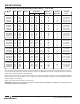
SPECIFICATIONS Circuit Breaker and Fused Disconnect Switch Sizes — 6 to 30 kW Model LI663CFC LI663CFD LI663CFE LI663CFF LI663CFM LI693CFC LI693CFD LI693CFE LI693CFF LI693CFM LI6123CFC LI6123CFD LI6123CFE LI6123CFF LI6123CFM LI6153CFC LI6153CFD LI6153CFE LI6153CFF LI6153CFM LI6183CFC LI6183CFE LI6183CFF LI6183CFM LI6243CFC LI6243CFD LI6243CFE LI6243CFF LI6243CFM LI6303CFC LI6303CFD LI6303CFE LI6303CFF LI6303CFM kW 6 6 6 6 6 9 9 9 9 9 12 12 12 12 12 15 15 15 15 15 18 18 18 18 24 24 24 24 24 30 30
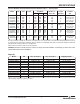
SPECIFICATIONS Circuit Breaker and Fused Disconnect Switch Sizes — 36 to 57 kW Model kW Volts Phase Amp Draw L1 L2 Breaker or Copper Conduit L3 Fuse Size Wire Size Size 125 108 54 175 250 150 70 2/0 250 kcmil 1/0 4 1-1/2" (38 mm) 2" (51 mm) 1-1/4" (32 mm) 1" (25 mm) 200 175 90 3/0 2/0 3 2" (51 mm) 1-1/2" (38 mm) 1" (25 mm) LI6363CFC LI6363CFD LI6363CFE LI6363CFF LI6363CFM 36 36 36 36 36 208 208 240 240 480 1 3 1 3 3 173 100 150 86.7 43.3 173 100 150 86.7 43.3 100 86.7 43.
INSTALLATION General For the most effective operation, install the booster water heater as close as possible to the commercial dish machine. The location must have a solid foundation or strong table/counter construction along with being clean and dry. Adequate front clearance is required to allow for accessibility to the control compartment. Location must have adequate clearance to allow for inspection, testing, or replacement of temperature/pressure relief valve. Figure 2.
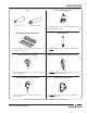
INSTALLATION Legs Plastic Leg Pressure Reducing Valve Stainless Steel Leg One pressure reducing valve with built-in bypass supplied with all booster water heaters. Mounting Brackets with Hardware Shock Absorber A set of mounting brackets or a set of legs are supplied with each booster water heater. An optional shock absorber is available for all booster water heaters.
INSTALLATION Temperature/Pressure Relief Valves Pressure Reducing Valve For protection against excessive pressures and temperatures in the booster heater, install temperature/pressure protective equipment required by local codes. The temperature/pressure relief valve supplied with this booster water heater is constructed with brass working parts and heat resistant silicone seat discs.
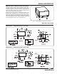
INSTALLATION Inlet Plumbing Connections Use the following procedures to connect the inlet and outlet water lines as well as inspect the system once the plumbing connections are complete. (Refer to Figure 5, 6, or 7) 1. Connect the booster water heater inlet to a hot water supply line from the regular water heater. Water temperature from the regular water heater should be 110° or 140°F (43° or 60°C) and should not exceed 160°F (71°C).
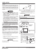
INSTALLATION Temperature/Pressure Gauge Temperature/Pressure Relief Valve 150 psi (1034 kPa)/210°F (99°C) Temperature/Pressure Gauge Outlet Pressure Reducing Valve w/Bypass. Maximum 20 psi (138 kPa) flow pressure. 3/4″ Gate or Ball Valve* Shock Absorber † Outlet to dish machine Water inlet from regular water heater 3/4″ Union* Inlet Blended Phosphate Water Treatment System † Drain Valve* 3/4″ Union* Floor Drain Discharge from T/P relief valve. Air gap must comply with plumbing code.
INSTALLATION Outlet 1. Using a 3/4″ union and piping, connect the booster water heater outlet to the commercial dish machine sanitizing rinse pipe connection. CAUTION DO NOT turn on power to the booster water heater until tank has been filled with water and all air has been vented through dish machine rinse nozzle. The heating elements will burn out in seconds if operated when they are not immersed in water.
OPERATION 8. When the booster water heater has had sufficient heating time, operate the rinse cycle and check the water temperature and pressure readings on the gauges. General Use the following procedures to operate the Magnum Series Commercial Electric Booster water heater. Water temperature at the booster outlet should be 185°–190°F (85°–88°C) and flow pressure should be 20 psi (138 kPa) maximum. WARNING NOTE: Outlet water temperatures can be adjusted for low-temperature dish machine applications.
MAINTENANCE General Bradford White Magnum Series Commercial Electric Booster water heaters are designed for maximum durability and performance, with minimum maintenance. Outer Adjustment Screw WARNING ELECTRIC SHOCK HAZARD: • Turn power OFF at disconnect switch/circuit breaker and allow unit to cool before performing any maintenance or cleaning. Inner Adjustment Screw Figure 12. Thermostat Adjustment • This unit must be serviced by qualified personnel only.
MAINTENANCE High Temperature Limit Safety Switch Blended Phosphate Treatment System (optional) Bradford White Commercial Electric Booster water heaters are equipped with a manually reset high temperature limit safety switch. If the temperature of the water in the heater exceeds 210°F (99°C) the safety switch will shut off the power. The switch must be reset manually by pushing the red button. Use the following procedure if the high temperature limit safety switch needs to be reset.
TROUBLESHOOTING GUIDE Symptom Water reaches 180°F (82°C) but does not last through the entire dishwasher operation. Probable Cause Corrective Action Low incoming water temperature. Incoming water temperature drops. Flow pressure is too high. Booster water undersized. heater may be Incorrect voltage. The booster heater does not heat at all or only delivers water at 120°–150°F (49°–66°C). Unit may have been energized without water (dry fired).
TROUBLESHOOTING GUIDE Symptom Water at dish machine is not at the proper temperature. Probable Cause Gauge(s) not working properly. Thermostat set too low. Heating elements burn out. Booster heater has more than 5 linear feet (1524 mm) of water pipe to the dishwasher, causing the water to cool off inside the pipe. Tank inadvertently drained leaving elements in a dry condition. Lime buildup in tank causing elements to split and burn out. Relief valve dribbles.
ACCESSORIES Stainless Steel Adjustable Legs Floor Mounting Hardware 1. Carefully place the unit on its side. Stainless steel adjustable legs with deck mounting flange are available for securing the booster heater to the floor. NOTICE Shock Absorber The shock absorber installed between the booster and the commercial dish machine reduces water hammer induced by rapidly operating valves. The water hammer can cause damage to the equipment. Do not lay unit on the side with the control panel.
WIRING DIAGRAMS 6 – 9 kW Wiring Diagram, All Voltages, Single- or Three-Phase 10-01-454 12 – 18 kW Wiring Diagram, All Voltages, Three-Phase 10-01-448 18 Form No.
WIRING DIAGRAMS 12 – 15 kW Wiring Diagram, 208 and 240 V, Single-Phase 10-01-452 18 kW Wiring Diagram, 208 and 240 V, Single-Phase 10-01-447 Form No.
WIRING DIAGRAMS 24 – 30 kW Wiring Diagram, 240 V, Single-Phase 10-01-432 24 – 36 kW Wiring Diagram, 208 and 240 V, Three-Phase 10-01-433 20 Form No.
WIRING DIAGRAMS 24 – 36 kW Wiring Diagram, 480 V, Three-Phase 10-01-435 36 kW Wiring Diagram, 240 V, Single-Phase 10-01-436 Form No.
WIRING DIAGRAMS 36 – 57 kW Wiring Diagram, 208 and 240 V, Three-Phase 10-01-437 45 – 57 kW Wiring Diagram, 480 V, Three-Phase 10-01-434 22 Form No.
LIMITED COMMERCIAL WATER HEATER WARRANTY WHAT DOES THIS LIMITED WARRANTY COVER? This limited warranty covers both the tank and component parts for leakage or other malfunction caused by defects in materials and/or workmanship. It extends to the first buyer and to any subsequent owner(s) as long as the water heater remains installed at its original place of installation. HOW DOES STATE LAW RELATE TO THE WARRANTY? Some states do not allow: 1. Limitations on how long an implied warranty lasts. 2.
LIMITED COMMERCIAL WATER HEATER WARRANTY (CONTINUED) WHAT SHOULD YOU DO TO KEEP THE WARRANTY IN EFFECT? To facilitate warranty assistance, you should: SPECIAL STATE PROVISIONS For water heaters installed in California or Oregon, Paragraphs 2(c) (i) (iv) of the paragraph “WHAT DOES THIS WARRANTY NOT COVER?” does not apply. 1. Follow all instructions enclosed with the product. 2. Retain all bills of sale or receipts for proof of installation, etc.
NOTES Form No.
Ambler, PA 19002 Technical Service 800.334.3393 Service Parts 800.538.2020 Warranty Service 800.531.2111 www.bradfordwhite.com Printed in U.S.A. October 2009 Part No. 07.04.474.00 Form No.