Instructions for: TTW 1 Universal Service Replacement Blower Kit P/N 265-47200-00 (To be performed ONLY by qualified service providers) The Blowers on the Following Water Heaters are Serviced by This Kit: MITW -10 Series MITW -12 / -15 Series M1TW Series (Normal & High Altitude) (For full model numbers, see page 2.
Model Numbers Reference M1TW Series MITW -12 / -15 Series MITW -10 Series Water Heater Model Numbers Serviced by This Kit Water Heater Model Numbers Original Blower’s P/N MITW40L*LN10 MITW40L*CX10 MITW50L*LN10 MITW50L*CX10 239-39785-00 MITW40L*EN12 MITW40L*BN12 MITW40L*CX12 MITW50L*EN12 MITW50L*BN12 MITW50L*CX12 239-41605-00 MITW40L*EN15 MITW40L*BN15 MITW40L*CX15 MITW50L*EN15 MITW50L*BN15 MITW50L*CX15 239-41605-00 M1TW40S*BN M1TW40S*CX M1TW50S*BN M1TW50S*CX 239-45584-00 243-45987-00 (Hi-Alt) M
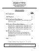
Kit Components 3 2 10 4 7 8 13 5 9 1 11 12 1 2 3 4 5 6 7 8 9 10 11 12 13 Part Number 265-47195-00 239-47194-00 239-47193-00 239-46263-00 239-47196-00 239-47199-00 265-44072-01 239-44113-00 239-47190-00 239-47192-01 239-47191-00 238-47197-00 239-47281-00 Qty 1 1 1 1 1 1 1 5 1 1 1 1 2 Description Universal Blower Wire Harness MITW-12/15 Series Wire Harness MITW-10 Series 2" Exhaust Adapter & Vent Terminal Kit Transformer Junction Box Transformer Junction Box Cover Transformer (120V / 24V) Screws
Tools Required ¼" Nut Driver 5/16" Nut Driver Slotted Screwdriver Philips Screwdriver Hammer 1/8" Drill Bit Drill Channel Lock Pliers Needle Nose Pliers Tape (preferably scotch or masking) PVC Primer / Cement Wire Cutters Wire Strippers Wire Brush Hacksaw Page 4
Bradford White TTW 1 Universal Service Replacement Blower Kit P/N 265-47200-00 Table of Contents Kit Components Page 3 Tools Required 4 MITW -10 Series Water Heaters: 6 MITW40L*LN10, MITW40L*CX10, MITW50L*LN10, MITW50L*CX10 MITW -12 / -15 Series Water Heaters: 12 MITW40L*EN12, MITW40L*BN12, MITW40L*CX12, MITW50L*EN12, MITW50L*BN12, MITW50L*CX12, MITW40L*EN15, MITW40L*BN15, MITW40L*CX15, MITW50L*EN15, MITW50L*BN15, MITW50L*CX15 M1TW Series Water Heaters: 21 M1TW40S*BN, M1TW40S*CX, M1TW50S*BN, M1T
TTW1 Universal Service Replacement Blower MITW -10 Series Note: This set of instructions is for the following model numbers: MITW40L*LN10, MITW40L*CX10, MITW50L*LN10, and MITW50L*CX10. Note: The following parts are required to convert the model numbers shown above: Template, Flue Restrictor, Screws, Wire Harness MITW-10 Series, Universal Blower, Wire Nuts, and 2" Exhaust Adapter / Vent Terminal Kit. Please refer to the Kit Components page (Page 3) for a picture of each item. Step 1.
TTW1 Universal Service Replacement Blower MITW -10 Series Step 4. Remove the screws, qty. (4), that secure the blower to the jacket head. Step 5. Remove blower from the top of the water heater. Remove any loose debris and tools from the top of the water heater, including any portion of the blower gasket that still exists. Warning: Step 6. Failure to locate the blower correctly will result in improper water heater operation.
TTW1 Universal Service Replacement Blower MITW -10 Series Warning: Step 7. Warning: Step 8. Failure to install flue restrictor will result in improper water heater operation. Install the flue restrictor, P/N 239-47191-00, firmly on the flue. It may be necessary to lightly tap down the flue restrictor. Be sure to tap it evenly and straight down. Wire brush the top of the water heater if rust or corrosion exists. Place flue restrictor on flue. Do NOT remove Torx head screws from universal blower.
TTW1 Universal Service Replacement Blower MITW -10 Series Cut just below these crimp connectors. Then, remove (1) white and (1) green wire from bundles. Trace wires back to power cord. Step 8. c.) Just below the crimp connector, cut the (3) white (neutral) wires. Remove the white power cord lead from the bundle.
TTW1 Universal Service Replacement Blower MITW -10 Series Step 9. a.) Ensure that the pressure switch, P/N 239-47192-02, is mounted in the vertical position, as shown. This pressure switch comes standard in the blower from the factory. Its vacuum setting should read -0.80" wc. b.) Place the access compartment cover back on the blower and secure with (3) screws from Step 8a.
TTW1 Universal Service Replacement Blower MITW -10 Series Step 12. Find the rubber vent adapter kit, P/N 239-46263-00, provided with the blower kit. Install the 2” vent adapter on the exhaust side of the universal blower. Discard the vent terminal included with the vent adapter kit. Be sure that vent pipe is properly seated in the top side of vent adapter.
TTW1 Universal Service Replacement Blower MITW -12 / -15 Series Note: This set of instructions is for the following model numbers: MITW40L*EN12, MITW40L*BN12, MITW40L*CX12, MITW50L*EN12, MITW50L*BN12,MITW50L*CX12, MITW40L*EN15, MITW40L*BN15, MITW40L*CX15, MITW50L*EN15, MITW50L*BN15, and MITW50L*CX15.
TTW1 Universal Service Replacement Blower MITW -12 / -15 Series Step 4. Remove the screws, qty. (3), that secure the blower to the jacket head. Unscrew (3) screws that hold blower to the jacket head. Blower junction box Step 5. Disconnect blower wire harness from receptacle, located in the jacket head under the blower junction box. The white connector must be pinched to remove. Unplug blower harness from jacket head receptacle by pinching the connector. Step 6. Warning: Step 7.
TTW1 Universal Service Replacement Blower MITW -12 / -15 Series Slip the template over the water connections. It is not necessary to remove the pipes connected to the water heater’s inlet and outlet. Step 7. b.) Place the template on top of the water heater, being sure to have the arrows point towards the front of the water heater, which is the side where the drain and gas valve are located. Tape the template to the top of the water heater to hold it in place.
TTW1 Universal Service Replacement Blower MITW -12 / -15 Series Black wire Step 9. b.) Inside the access compartment, follow the black wire from the power cord until you reach the flag terminal attached to the end of the wire. Disconnect black wire from the back of the power inlet connector. Power inlet connector Remove black wire’s flag terminal Power cord Cut just below these crimp connectors. c.) Just below the crimp connector, cut Then, remove (1) white and (1) green the (3) white (neutral) wires.
TTW1 Universal Service Replacement Blower MITW -12 / -15 Series Step 9. f.) Verify that all electrical connections have been modified, as previously indicated. Also, verify that the pressure switch tubing is connected to the pressure tap on the blower and to the switch itself. Ensure that the tubing is not kinked. Step 10. a.) Ensure that the pressure switch, P/N 239-47192-02, is mounted in the vertical position, as shown. This pressure switch comes standard in the blower from the factory.
TTW1 Universal Service Replacement Blower MITW -12 / -15 Series Blower harness receptacles Step 12. a.) Position the junction box, P/N 239-47196-00, on top of the water heater, in front of the blower, and on the side nearest the T&P valve. b.) Place the transformer, P/N 265-44072-01, inside the junction box such that there is sufficient room between its (4) posts and the sidewalls of the junction box. Determine the side to remove a knock-out. Remove the transformer from the junction box.
TTW1 Universal Service Replacement Blower MITW -12 / -15 Series Step 13. Locate new blower harness, P/N 239-47194-00, provided with the kit. Route loose wire ends (yellow, blue, white, and green) through knock-out opening from Step 12c. Step 14. Fasten conduit connector to the junction box. Route wires through hole in junction box. Fasten connector to junction box. Step 15. Connect the wire terminals to their corresponding locations on the transformer: a.
TTW1 Universal Service Replacement Blower MITW -12 / -15 Series Step 17. Secure the junction box cover, P/N 239-47199-00, to the junction box. Tighten (2) screws on junction box to secure cover. Step 18. With the blower and transformer assembly fastened to the water heater, the remaining ends of the blower wire harness can now be attached with the cord sets to the blower and then the white connector to the receptacle in the jacket head. Plug cord sets into receptacles in blower.
TTW1 Universal Service Replacement Blower MITW -12 / -15 Series Step 20. If it has not already been done, remove the old vent adapter from the existing vent pipe. Step 21. If necessary, re-route the vent pipe such that it can be properly seated in the top portion of the vent adapter. Step 22. Be sure that both clamps on the vent adapter are firmly tightened, securing the blower, vent adapter, and vent pipe together. Step 23. Double-check all vent connections. Step 24.
TTW1 Universal Service Replacement Blower M1TW Series Note: This set of instructions is for the following model numbers: M1TW40S*BN, M1TW40S*CX, M1TW50S*BN, M1TW50S*CX, M1TW40S*FBN, M1TW40S*FCX, M1TW50S*FBN, M1TW50S*FCX, M1TW60T*FBN, and M1TW60T*FCX. Note: The following parts are required to convert the model numbers shown above: Screws, Universal Blower, Dilution Air Orifice, Pressure Switch (-0.70" wc, for high altitude only), and 2" Exhaust Adapter / Vent Terminal Kit.
TTW1 Universal Service Replacement Blower M1TW Series Step 4. Disconnect the vent pipe and adapter that are connected to the outlet of the blower. Unscrew both clamps that hold the adapter to the blower and vent pipe. Unscrew (3) screws that hold blower to the jacket head. Step 5. Remove the screws, qty. (3), that secure the blower to the jacket head. Step 6. Remove blower from the top of the water heater. Remove any loose debris and tools from the top of the water heater.
TTW1 Universal Service Replacement Blower M1TW Series Disconnect (2) flag terminals and tubing from pressure switch to remove. Step 7. b.) Replace the current pressure switch ONLY IF the model is for high altitude (2001 ft. & above). Warning: Failure to replace universal blower pressure switch for high altitude will result in improper water heater operation. Choose corresponding pressure switch from kit. Verify correct P/N and setting on label to match this model’s requirements, as shown in Step 7b.
TTW1 Universal Service Replacement Blower M1TW Series Step 8. b.) Place the access compartment cover back on the blower and secure it with its (3) screws from Step 7a. Start the lower screw first, and when doing so, make sure that the hole in the pressure switch’s bracket matches up to the hole in the blower housing. Step 9. Secure (3) cover screws. a.) Remove the intake boot from the rear of the blower. b.
TTW1 Universal Service Replacement Blower M1TW Series Step 9. c.) Replace the intake boot back onto the blower. If it is necessary, the cable, or zip, tie can be removed from the boot to allow for easier assembly. Replace boot on rear of blower. Remove cable tie if boot will not go onto rear of blower easily. Step 10. Boot back in place. Now that the universal blower is properly modified for a M1TW series water heater, the blower can be properly positioned and secured on top of the water heater.
TTW1 Universal Service Replacement Blower M1TW Series Step 12. Find the rubber vent adapter kit, P/N 239-46263-00, provided with the blower kit. Install the 2” vent adapter on the exhaust side of the universal blower. Discard the vent terminal included with the vent adapter kit. Be sure that vent pipe is properly seated in the top side of vent adapter.
Notes NOTES Page 27