
Installation / Operation Instruction Manual


page 2
GENERAL SYSTEM OPERATION
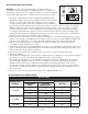
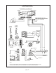
POWER VENTER KITS FOR 24 VOLT CONTROLS (CK-41 CONTROL KIT)
The water heater aquastat contacts close and the flue damper (if part of water heater) opens. When the 1.
damper opens all the way, the end switch contacts in the damper motor close, completing the 24 volt
circuit to the CK-41 control box causing the motor relay contacts to close and start the power
venter motor.
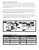
When the power venter blower reaches operating speed, the resulting vacuum causes the pressure 2.
switch contacts to close. The 24 volt control circuit flows through the pressure switch contacts in the CK-
41 control box and through the normally closed spillage switch contacts on the draft hood, completing
the circuit to the ignition module on the water heater control box. The ignitor lights the pilot and the main
gas valve opens causing the main burners to light.
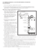
If the venting system becomes disconnected or plugged between the power venter and the water heater 3.
vent connection, the flue products will spill out of the draft hood relief opening, heat up the spill switch
temperature disc and cause the contacts to open and interrupt power to the ignition module causing the
gas valve to close and stop the burners. If the power venter blower fails to operate, the pressure switch
contacts will not close and the burners remain off.
When the aquastat is satisfied, the contacts open and stop the power venter, interrupting power to the 4.
ignition module and gas valve, and the flue damper closes.
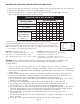
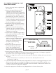
ITEMS INCLUDED IN KIT (CK-41):
1- Junction box with mounted pressure switch and
relay base
1- 24 volt relay for controlling power venter motor
1- 1 ft. length of
1
⁄4" aluminum tubing
1-
1
⁄4" tubing connector
1- flexible metal clad conduit
1- GSK-3 spillage switch
1- wiring harness (30 ft. length) to connect power
venter control to water heater controls
3- cable clamps to fasten the harness
ITEMS INCLUDED IN KIT (CK-81):
1- Junction box with mounted pressure switch
1- 115V to 24V transformer
1- 24 volt relay
1- 1 ft. length of
1
⁄4" aluminum tubing
1-
1
⁄4" tubing connector
1- flexible metal clad conduit
1- GSK-3 spillage switch
1- wiring harness (30 ft. length) to connect power
venter control to water heater controls
3- cable clamps to fasten the harness
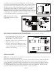
POWER VENTER KIT FOR MILLIVOLT CONTROLS (CK-81 CONTROL KIT)
When the aquastat contacts close, the 24 volt circuit is completed from the transformer, through the 1.
wiring harness and switch contacts, and through the relay coil causing the motor relay contacts to close
and start the power venter blower.
When the blower reaches operating speed, the vacuum near the blower causes the pressure switch 2.
contacts to close and complete the millivolt circuit through the normally closed spill switch contacts to the
gas valve, allowing main gas to flow to the burners and ignite from the pilot.
If the venting system becomes disconnected or plugged between the power venter and the water heater 3.
vent connection, the flue products will spill out of the draft hood relief opening, heat up the spill switch
temperature disc and cause the contacts to open and interrupt the millivolt circuit to the gas valve and
stop all gas flow. If the power venter blower fails to operate, the pressure switch contacts will not close
and the burners remain off. If the pilot becomes extinguished, the thermopile stops generating millivolt
power and the gas valves remain closed until the pilot is relit.
When the aquastat is satisfied, the contacts open and stop the power venter, causing the power to be 4.
interrupted to the ignition module and gas valve, and the flue damper closes.